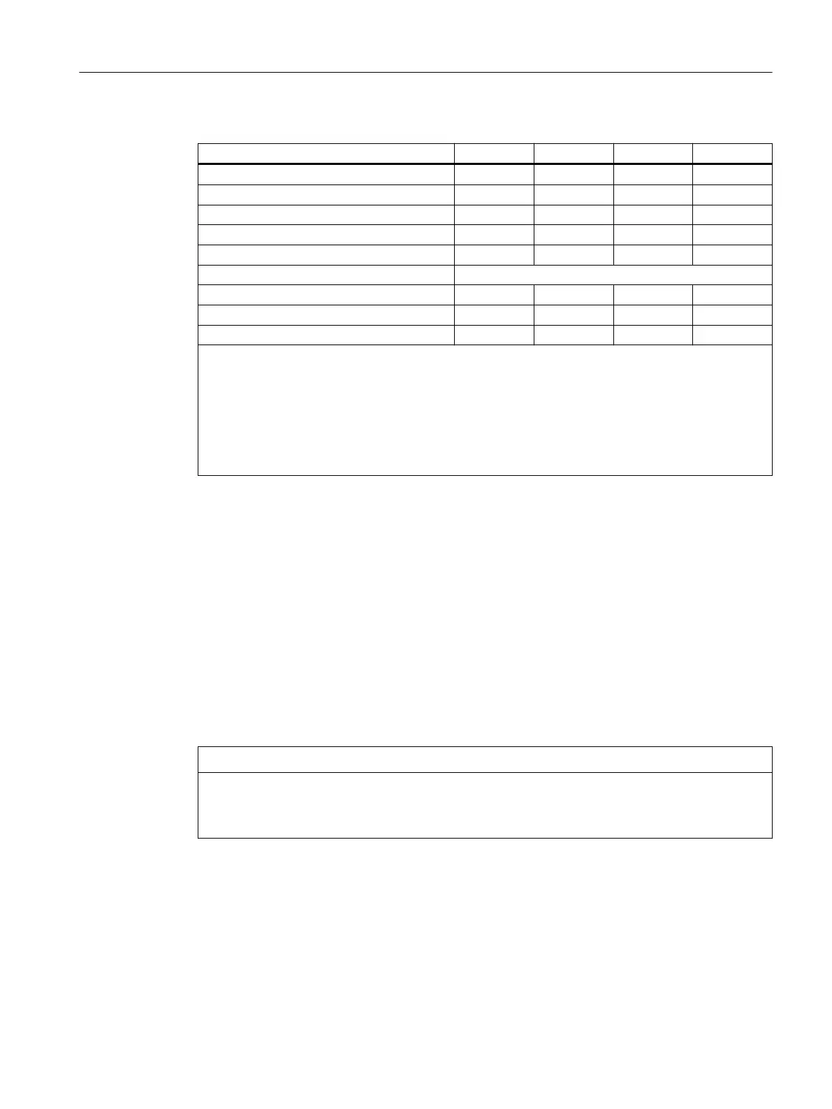
Table 9-46 Electrical specication of the digital outputs
Digital outputs min. Standard max. nominal
High-level voltage (U
H
) V
CC
- 3 V
1)
V
CC
24 V
Output current I
OUT
- - 250 mA
2)
-
Voltage with low level (U
L
) - - - Output open
Leakage current at low level - 50 μA 400 μA -
Signal delay time T
PHL
- 0.5 ms - -
Maximum switching frequency
Resistive load - - 100 Hz -
Inductive load - - 2 Hz -
Lamp - - 11 Hz -
•
1)
U
H_typical
= V
CC
- I
OUT
× R
ON
V
CC
: Current operating voltage
I
OUT
: Output current
Maximum short-circuit current: 4 A (max. 100 μs, V
CC
= 24 V)
R
ON
: Maximum internal resistance = 0.4 Ω
•
2)
Where demand factor is 100% (all outputs active)
• Incorrect connection causes neither high level nor destruction of the outputs.
9.3.4.5 Analog X3 inputs/outputs
Cable specication
• Connectors: 12-pin socket/plug combination
• Cable: shielded
– max. cable length: 30 m
– max. connectable core cross-section: 0.5 mm
2
Wiring analog inputs/outputs
NOTICE
Shield support
If the analog inputs/outputs are wired, a shielded lead must be used. The shield must be
supported.
Procedure:
1. Strip cable for analog signals.
2. Secure the stripped connection piece of the cable with the shield connection clamp.
Connectable components
9.3 PP 72/48D 2/2A PN
NCU 7x0.3B PN
Equipment Manual, 10/2020, 6FC5397-1EP40-6BA1 133

 Loading...


