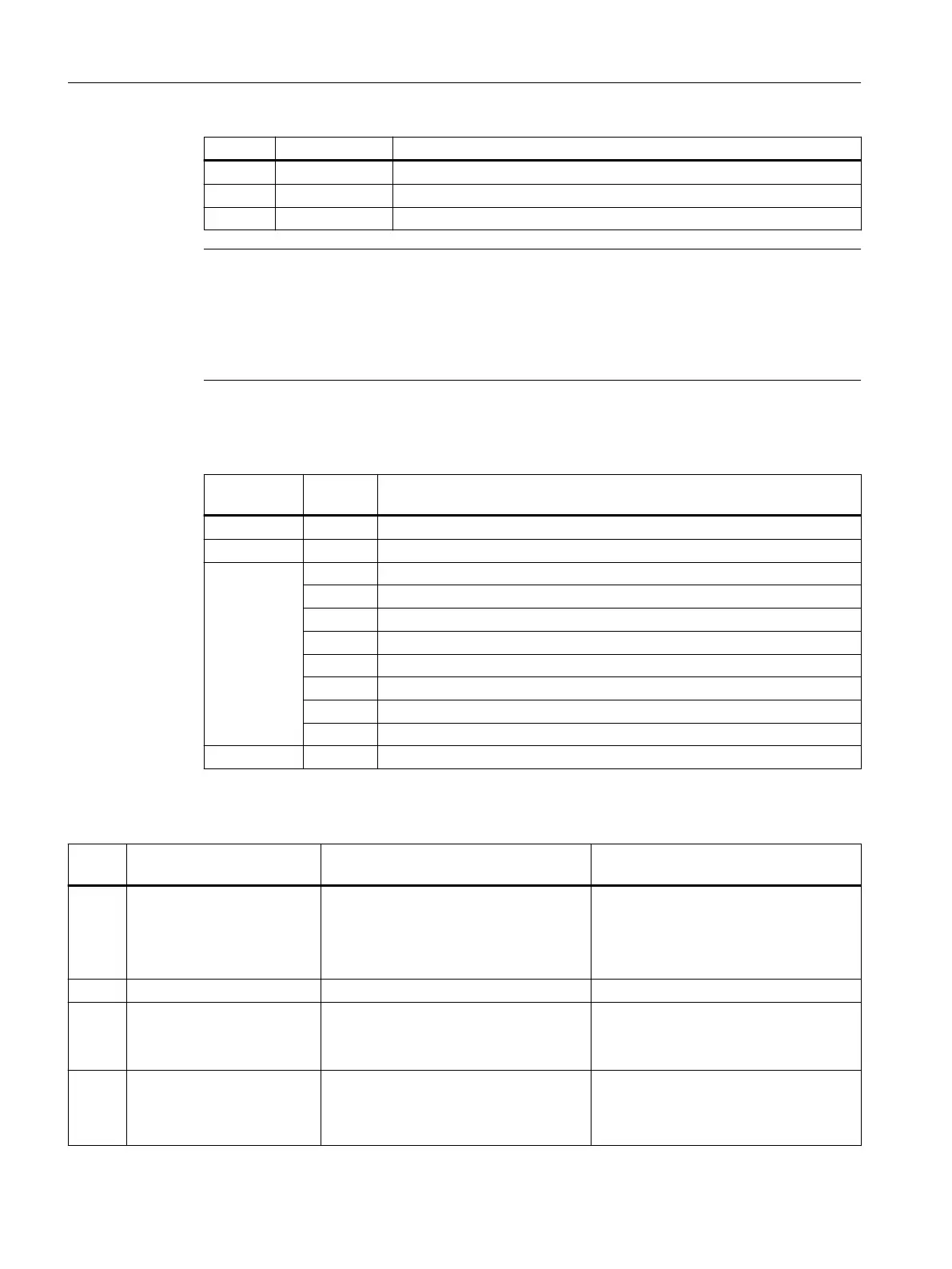
Bit Signal name Message
2 Diag_2 Overload DO byte 5/4
1 Diag_1 Overload DO byte 3/2
0 Diag_0 Overload DO byte 1/0
Note
The "alive and well" counter is a 3 bit modulo counter at the PP application level. The PP
application can be monitored using this counter. Failure of the application software does not
generally result in a communication failure, as this is developed in a hardware-supported
manner. The watch dog switches o the digital outputs, while the inputs remain at their last set
values.
Table 9-64 Overview of the messages in byte 1, depending on the "alive and well" counter
"alive and
well" counter
Value
byte 1
Message
0 0 Reserved
1 Temperature value
2 0 No error
1 Impermissible input voltage in the temperature measurement mode
2 Reserved
3 Overload at the outputs
4 Incorrect operating mode selection
5 Internal error, system error
6 Range exceeded at the inputs
7 Range exceeded at the outputs
3 ... 7 0 Reserved
Table 9-65 Elimination of error for "alive and well" counter status "2"
Value
byte 1
Cause Eect Remedy
1 In the temperature measure‐
ment operating mode, an in‐
put voltage is too high. The
hardware may become dam‐
aged/destroyed as a result.
The "PNFault" LED is activated.
The outputs are disabled.
1)
The value 0x80 is stored in status byte 1.
It is essential that a Pt100 element is con‐
nected to terminals 3.4 or 7.8.
The module must be restarted with Power
ON after the error has been eliminated.
2 Reserved - -
3 Overload at the outputs The "PNFault" LED is activated.
The outputs are disabled.
1)
The value 0x80 is stored in status byte 1.
Check the loads at the analog output.
The module must be restarted with Power
ON after the error has been eliminated.
4 Incorrect operating mode se‐
lection, e.g. temperature
measurement at the analog
outputs.
Selection of operating mode is rejected, If selected correctly, the module switches
to cyclic operation.
Connectable components
9.3 PP 72/48D 2/2A PN
NCU 7x0.3B PN
144 Equipment Manual, 10/2020, 6FC5397-1EP40-6BA1

 Loading...


