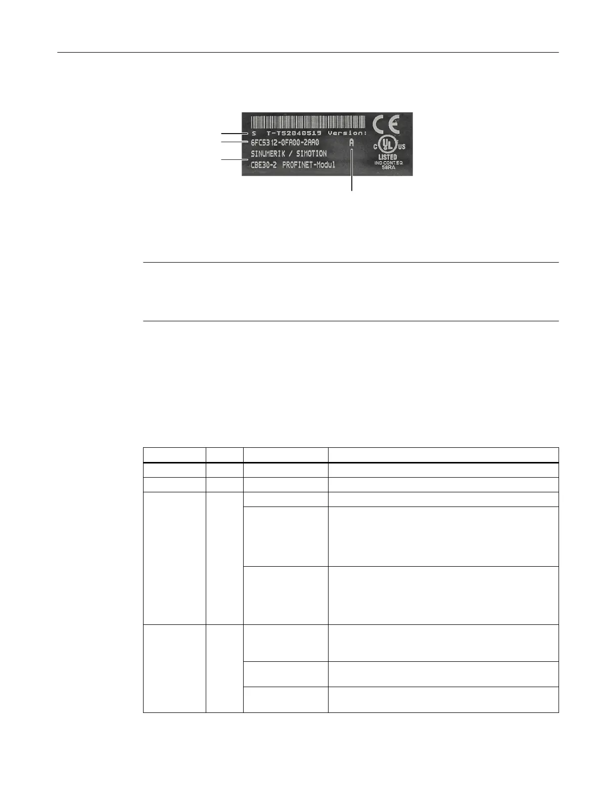
The following diagram shows you all of the information provided on the type plate.
Serial number
Order number
Module designation
HW version
Figure 9-24 CBE30-2 type plate
This plate is only visible, when the option board has been removed; it is attached to the
underside of the option board.
Note
The contents of the individual type plate elds on the actual option board may dier from those
described in this manual (e.g. updated product status, approvals and markings not yet issued,
etc.).
LED displays
The four ports of the X1400 interface provide integrated LEDs for displaying the link and the
activity. The front panel of the CBE30-2 is also tted with two LEDs (Fault and Sync), which
indicate the bus status.
Table 9-71 LED displays
Name Color Status Meaning
Link port Green lit The physical connection exists.
Activity port Yellow lit Data is being received or transmitted.
Fault Red o CBE runs without errors, data is being exchanged.
lit Bus fault:
• No physical connection to a subnet/switch
• Incorrect transmission rate
• Full duplex transmission is not activated.
ashing (2 Hz)
• Failure of a connected NCU
• At least one of the assigned NCUs cannot be ad‐
dressed
• Incorrect or no conguration.
Sync Green o Clock cycle system of the NCU is not synchronized to the
send cycle. An internal substitute clock of the same size
as the send clock is generated.
lit Clock cycle system of the NCU has synchronized to the
send cycle and data exchange is running.
ashing (0.5 Hz) Clock cycle system of the NCU has synchronized to the
send cycle and cyclic data exchange is running.
Connectable components
9.5 CBE30-2
NCU 7x0.3B PN
Equipment Manual, 10/2020, 6FC5397-1EP40-6BA1 151

 Loading...


