6 Assi
nin
Parameters to the Control and the PLC Pro
ram
6
03.96
6.10 Linear motors (1FN1 and 1FN3 motors)
6-169
Siemens AG 2000 All Rights Reserved
SINUMERIK 840D Installation and Start-Up Guide (IAD) – 04.00 Edition
6.10.6 Measuring system
The control direction of an axis is correct if the positive direction of the drive
(= CW rotating field U, V, W) coincides with the positive count direction of the
measuring system.
Note
The instructions for determining the drive direction apply only to Siemens mo-
tors (1FNx motors).
If the positive direction of the drive and positive count direction of the measur-
ing system do not coincide, then the actual speed value must be inverted (MD
32110) in the “Measuring system/Encoder” dialog during start-up.
It is also possible to check the control direction by parameterizing the drive first
and then moving it manually with the enabling signals inhibited.
If the axis is moved in a positive direction (see definition in Fig. 6-35), then the
actual velocity value must be counted positively.
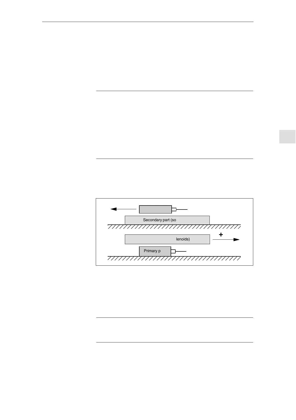
The direction of the drive is positive if the primary part moves in the opposite
direction to the outgoing cable in relation to the secondary part.
Secondary part (solenoids)
+
Secondary part (solenoids)
+
Primary part Outgoing cable direction
Primary part
Outgoing cable direction
Fig. 6-35 Determining the positive direction of the drive
The method by which the count direction is determined depends on the measur-
ing system itself.
1. Heidenhain measuring systems
Note
The count direction of the measuring system is positive if the distance between
the scanning head and rating plate increases (see Fig. 6-36).
Determine the
control direction
Determine the
drive direction
Calculate the
count direction of
the measuring
system
04.00

 Loading...


