9
9-197
Siemens AG 2000 All Rights Reserved
SINUMERIK 840D Installation and Start-Up Guide (IAD) – 04.00 Edition
Axis and Spindle Dry Run
9.1 Preconditions
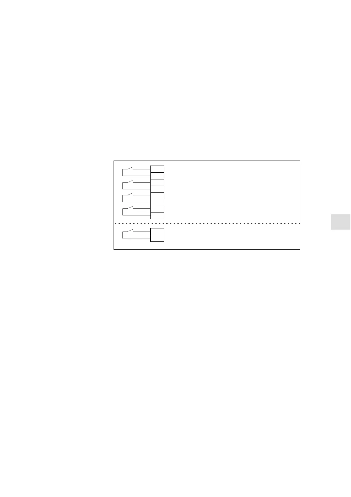
To allow an axis to be traversed from the control system, it is necessary to
supply enabling terminals on the drive and to set enabling bits on the interface.
Pulse enable
+24 V
+24 V
63
9
64
9
48
9
drive enable signal
DC link start
+24 V
Pulse enable
+24 V
669
Mains supply module
Drive module
setting-up mode
+24 V
112
9
References: /PJ/, Planning Guide for SIMODRIVE 611–A/611–D
The following signals must be made available at the PLC interface for axis or
spindle:
IS “Controller enable” (DB31–48, DBX2.1)
IS “Pulse enable” (DB31–48, DBX21.7)
IS “Position measuring system 1 or 2” (DB31–48, DBX1.5, DBX 1.6)
The following signals on the interface must not be set or else the axis/spindle
motion will be disabled:
IS “Feed/spindle override switch” (DB31–48, DBB0) not at 0%
IS “Axis/spindle disable” (DB31–48, DBX1.3)
IS “Follow-up mode” (DB31–48, DBX1.4)
IS “Distance to go/spindle reset” (DB31–48, DBX2.2)
IS “Feed stop/spindle stop” (DB31–48, DBX4.3)
IS “Traverse key disable” (DB31–48, DBX4.4)
IS “Ramp function generator disable” (DB31–48, DBX20.1)
References: /FB/, A2, “Axis/Spindle Parking, Follow-Up, Enable
Controller”
Setting of hardware limit switches and interface signal check:
S Hardware limit switch PLUS DB31 – 48.DBX12.1
S Hardware limit switch MINUS DB31 – 48.DBX12.0
Axis
enabling
Enables
on the drive
Enabling via PLC
interface
Limit switches
9

 Loading...


