6 Assi
nin
Parameters to the Control and the PLC Pro
ram
6
03.96
6.10 Linear motors (1FN1 and 1FN3 motors)
6-175
Siemens AG 2000 All Rights Reserved
SINUMERIK 840D Installation and Start-Up Guide (IAD) – 04.00 Edition
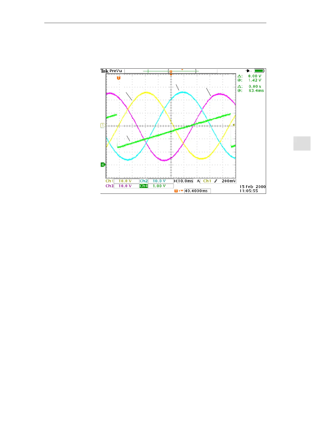
After the oscilloscope has been connected, the drive must be made to cross the
zero marker first in order to synchronize it.
Ch1/Phase U
Ch3/Phase W
Ch2/Phase V
Ch4
Fig. 6-44 Determining the commutation angle offset by measuring the EMF and normal-
ized electrical rotor position via DAC in a positive drive direction.
Definition of channels (Ch1 ... Ch4):
S Ch1: EMF phase U to neutral point
S Ch2: EMF phase V to neutral point
S Ch3: EMF phase W to neutral point
S Ch4: Normalized electrical rotor position via DAC measuring signal
With a synchronized drive, the difference between EMF/phase U and the electri-
cal rotor position must not exceed 10_.
If the difference is greater, the position of the zero marker must be moved in the
software in MD 1016 “COMMUNTATION_ANGLE_OFFSET”.
Determining the
commutation
angle
04.00
 Loading...


