2
03.96
2.2 Electrical configuration
2-31
Siemens AG 2000 All Rights Reserved
SINUMERIK 840D Installation and Start-Up Guide (IAD) – 04.00 Edition
X21
X20
18D
X1
X2
X11
X3
X4
X5X6
X7
X8
S1
S2
X10
X9
X153
X152
X151
D12
SIEMENS
X142X141
X13
ISA interface
NC keyboard
interface
Mass storage
interface IDE
PCMCIA optional
interface
Power supply
interface
LCD interface
External
keyboard/mouse
interface
Floppy disk
interface
Parallel printer interface
(LPT1)
VGA interface
Reset button
NMI button
Battery
X121 X122
COM1COM2
7-segment display
MPI interface for
connection of op-
erator panel
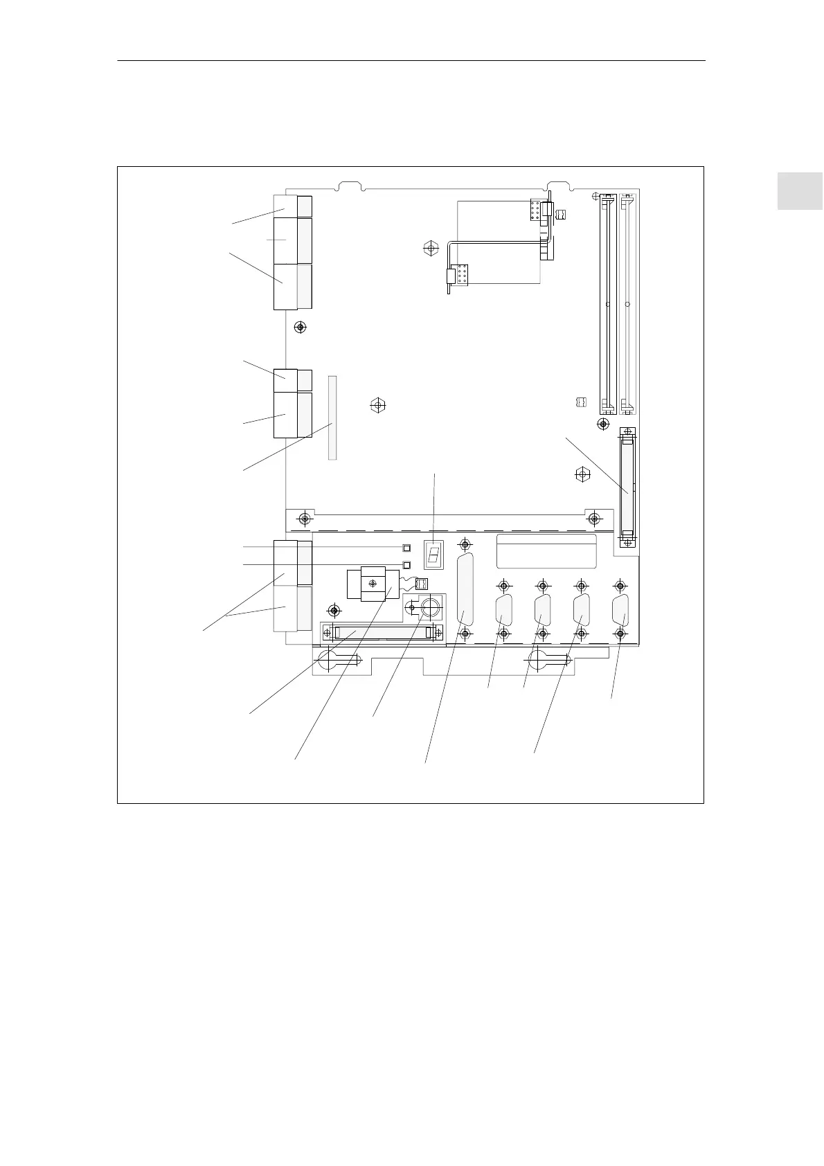
Fig. 2-12 Location of interfaces and control elements on MMC 101/102/103
The interfaces (e.g. pin assignments) are described and shown in detail in
References: /BH/, Operator Components Manual
MMC101, 102/103
Interfaces
2 Confi
uration

 Loading...


