Illustration
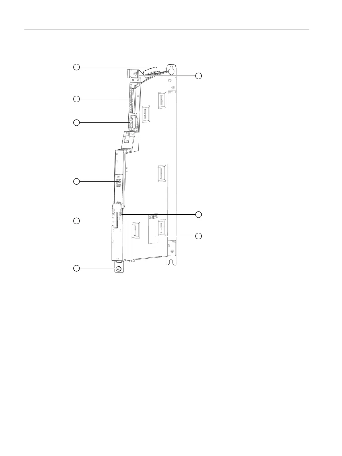
① Shield contact
② LEDs: RDY, DP
③ Nameplate
④ Functional grounding connection M5 / 3Nm
⑤ T0, T1, T2 Measuring sockets
⑥ RESET button
⑦ X124 Power supply
⑧ X122 Digital inputs/outputs
⑨ X100, X101, X102,
X103
DRIVE-CLiQ interfaces
Figure12-1 Illustration of the NX10.3 / 15.3 (without cover)
Connectable components
12.1NX10.3/NX15.3
NCU 1750
100 Equipment Manual, 10/2023, A5E45627807B AH
 Loading...


