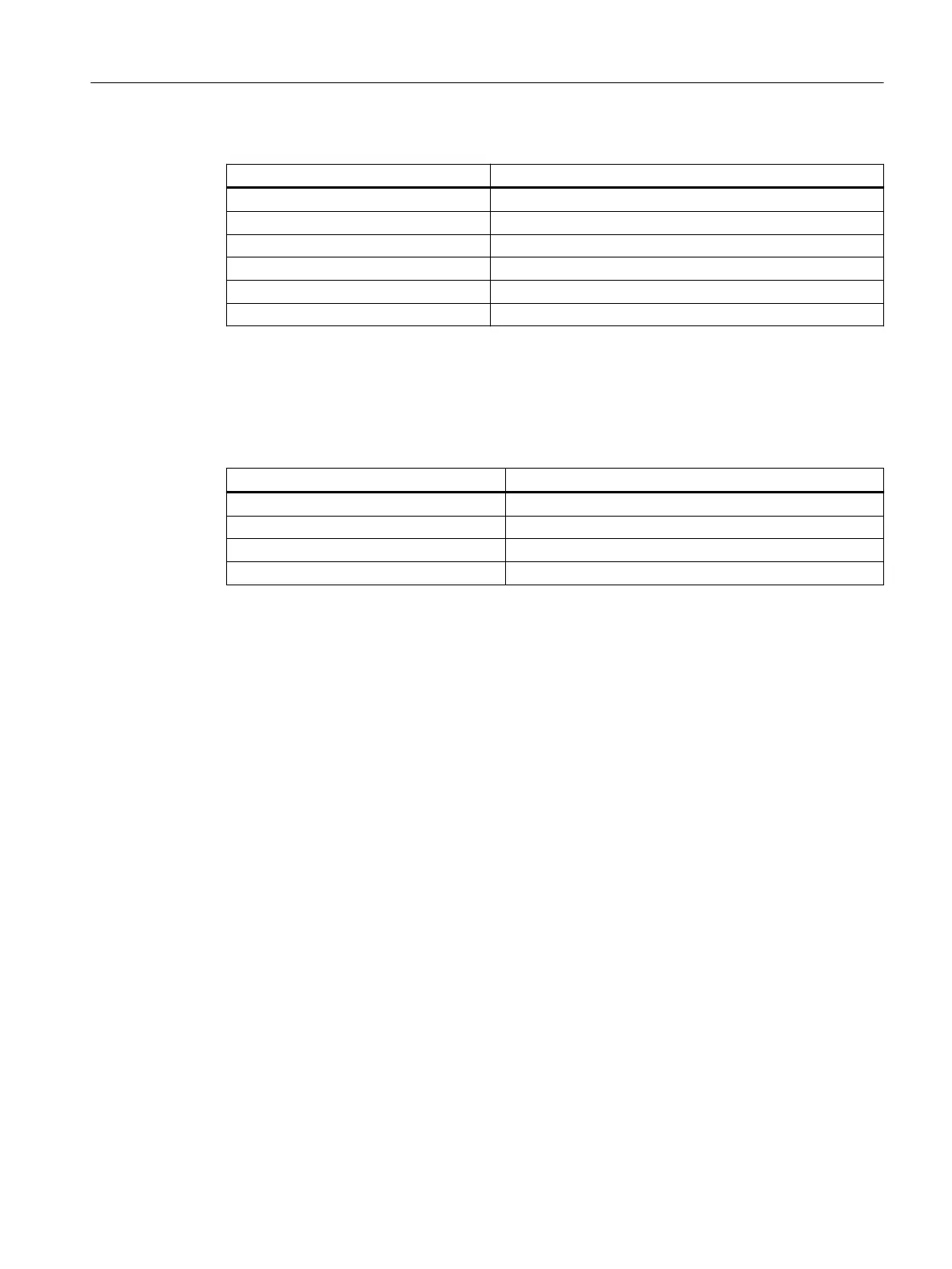
Table 8-15 Technical data for PROFIBUS cables
Characteristics Values
Wave impedance Approximately 135 to 160 Ω (f = 3 to 20 MHz)
Loop resistance ≤ 115Ω/km
Eective capacitance 30 nF/km
Damping 0.9 dB/100 m (f = 200 kHz)
Permissible conductor cross-section 0.3 mm
2
to 0.5 mm
2
Permissible cable diameter 8 mm + 0.5 mm
Cable lengths and data rate
The data rate determines the cable length of a subnet segment.
Table 8-16 Permitted cable length of a subnet segment for specic data rates
Data rate Max. cable length of a segment (in m)
19.6 to 187.5kbit/s 1000
1)
500kbit/s 400
1.5Mbit/s 200
3 to 12Mbit/s 100
1)
With isolated interface
Longer cable lengths:
If you must realize longer cable lengths than permitted in one segment, you must use RS485
repeaters. The maximum possible cable lengths between two RS485 repeaters correspond to
the cable length of a segment. You can connect up to 9RS 485 repeaters in series.
Note that an RS485 repeater must be counted as a subnet node when determining the total
number of nodes to be connected. This is true even if the RS485 repeater is not assigned its
own PROFIBUS address.
Connector features
The bus connector connects the PROFIBUS cables to the PROFIBUS DP interface X126, thus
establishing a connection to additional nodes.
Only bus connectors with a 35° cable outlet should be used in order to ensure that the front
cover can be closed.
8.9.3 Connection components in PROFIBUS
Connection components
Individual nodes are connected by means of bus connectors and PROFIBUS cables. Remember
to provide a bus connector with a programming port at either end of the subnet. This will give
you the option of expanding the subnet if required, for example, for a programming device.
Connecting
8.9PROFIBUS DP
NCU 1750
Equipment Manual, 10/2023, A5E45627807B AH 79
 Loading...


