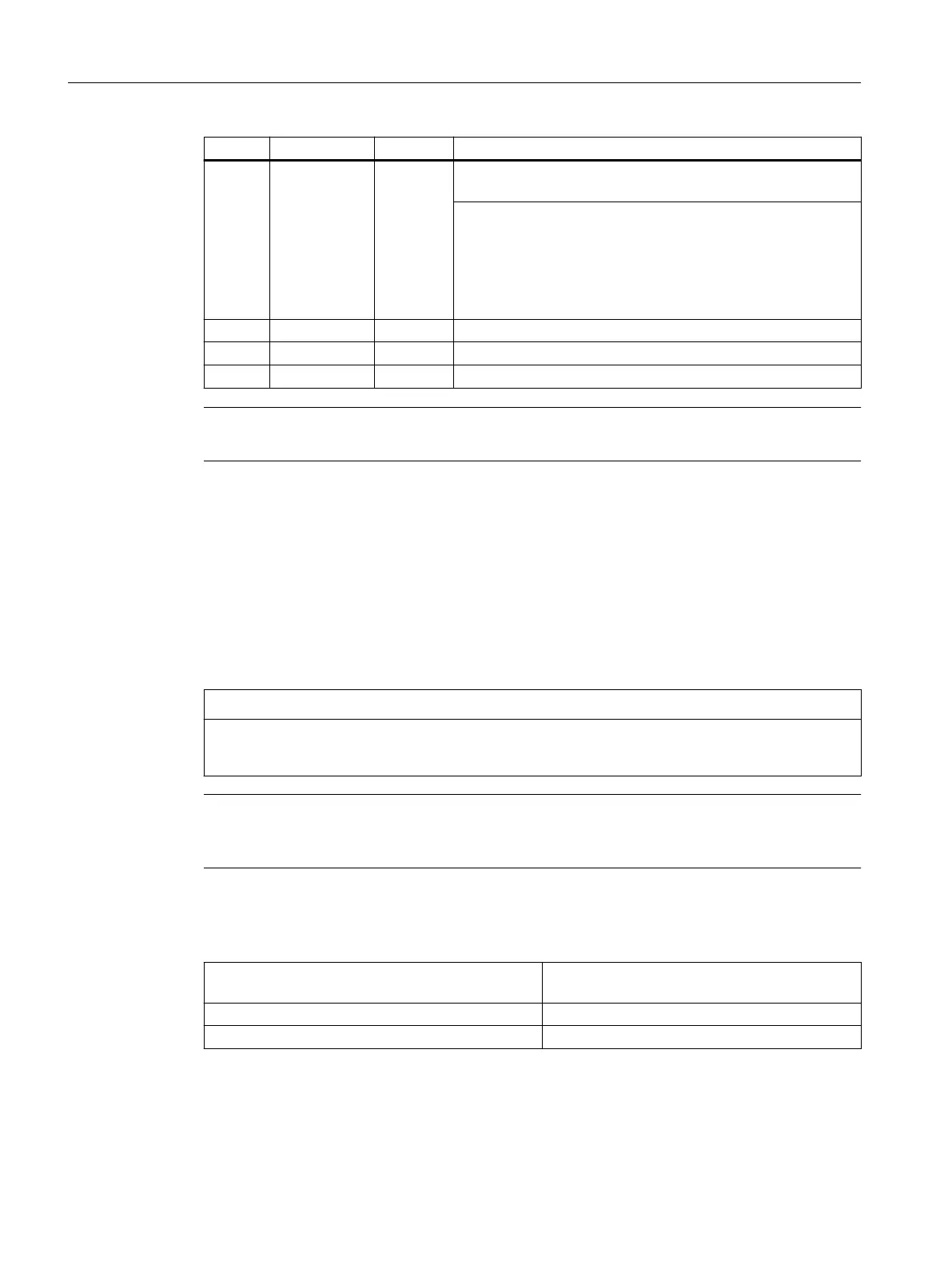
Name Designation Color Description
H3 PNFault Red Not lit: Module is operating without errors; the data exchange
with all congured I/O modules is running.
Lit: Severe bus error
One of the following errors is present at port1/port2:
• No physical connection to a subnet/switch
• Incorrect transmission rate
• Full duplex transmission is not activated
H4 DIAG1 Green Reserved
H5 DIAG2 Green Reserved
H6 OVTemp Red Overtemperature display
Note
When the system is booting, LEDs H1, H2 and H3 are lit.
12.2.2 Installation
12.2.2.1 Mounting
The I/O module is fastened to the wall of the control cabinet using a mounting plate and M6
screws. The module must be installed according to EN 60204.
NOTICE
The I/O module can be damaged if there is no ground connection
A protective conductor must be connected using the grounding screw.
Note
The type plate is tted to the rear side of the mounting plate. Note the relevant data because it
is no longer visible after installation.
Table 12-11 Mounting versions:
Portrait mounting at the lateral strap of the mount‐
ing plate
(2x screw M6).
Flat mounting at the rear wall of the mounting plate (4x screw M6).
Only use copper conductors as ground wire. AWG10 (2.5 mm2), the torque is 3 Nm.
Connectable components
12.2PP 72/48D PN and PP 72/48D 2/2A PN
NCU 1750
116 Equipment Manual, 10/2023, A5E45627807B AH
 Loading...


