Note
The fast digital inputs/outputs must be shielded.
8.10.3 Connecting digital inputs/outputs
Cable specication
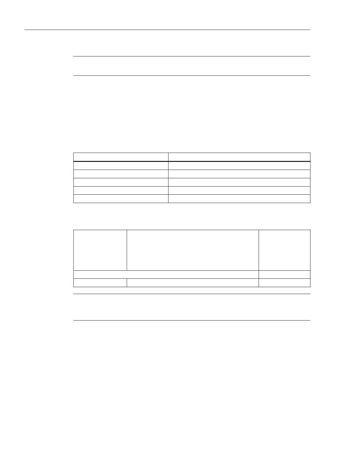
Table 8-21 Cable specication at X122 / X132 / X142
Features Version
Connector type 14-pin spring-loaded terminals
Number of cables that can be connected 1
Connection option 0.2 to 1.5 mm
2
Max. current carrying capacity 6 A
Max. cable length 30 m
Table 8-22 Connectable conductor cross-sections
Connectable conduc‐
tor cross-sections
Rigid
Flexible
Flexible, with end sleeve without plastic sleeve
Flexible, with end sleeve with plastic sleeve
AWG / kcmil
0.2 to 1.5 mm
2
0.2 to 1.5 mm
2
0.25 to 1.5 mm
2
0.25 to 0.75 mm
2
24 to 16
Stripped length 10 mm
Tool Screwdriver 0.4 x 2.0 mm
Note
To achieve optimum interference suppression, shielded cables must be used to connect
measuring inputs or BEROs.
The following cable lugs may be used:
• Crimped cable lug to DIN 46234
• Pressed cable lug to DIN 46235
• Tube-type cable lug to SN 71322
• Tube-type cable lug "Klauke R Series", UL Category ZMVV
Connecting
8.10Digital inputs/outputs
NCU 1750
88 Equipment Manual, 10/2023, A5E45627807B AH
 Loading...


