Terminal Byte Bit7 Bit6 Bit5 Bit4 Bit3 Bit2 Bit1 Bit0
X333
n+4 Pin38
DO 4.7
Pin37
DO 4.6
Pin36
DO 4.5
Pin35
DO 4.4
Pin34
DO 4.3
Pin33
DO 4.2
Pin32
DO 4.1
Pin31
DO 4.0
n+5 Pin46
DO 5.7
Pin45
DO 5.6
Pin44
DO 5.5
Pin43
DO 5.4
Pin42
DO 5.3
Pin41
DO 5.2
Pin40
DO 5.1
Pin39
DO 5.0
12.2.4.2 Assigning parameters to the analog inputs / outputs
Operating mode of the analog outputs
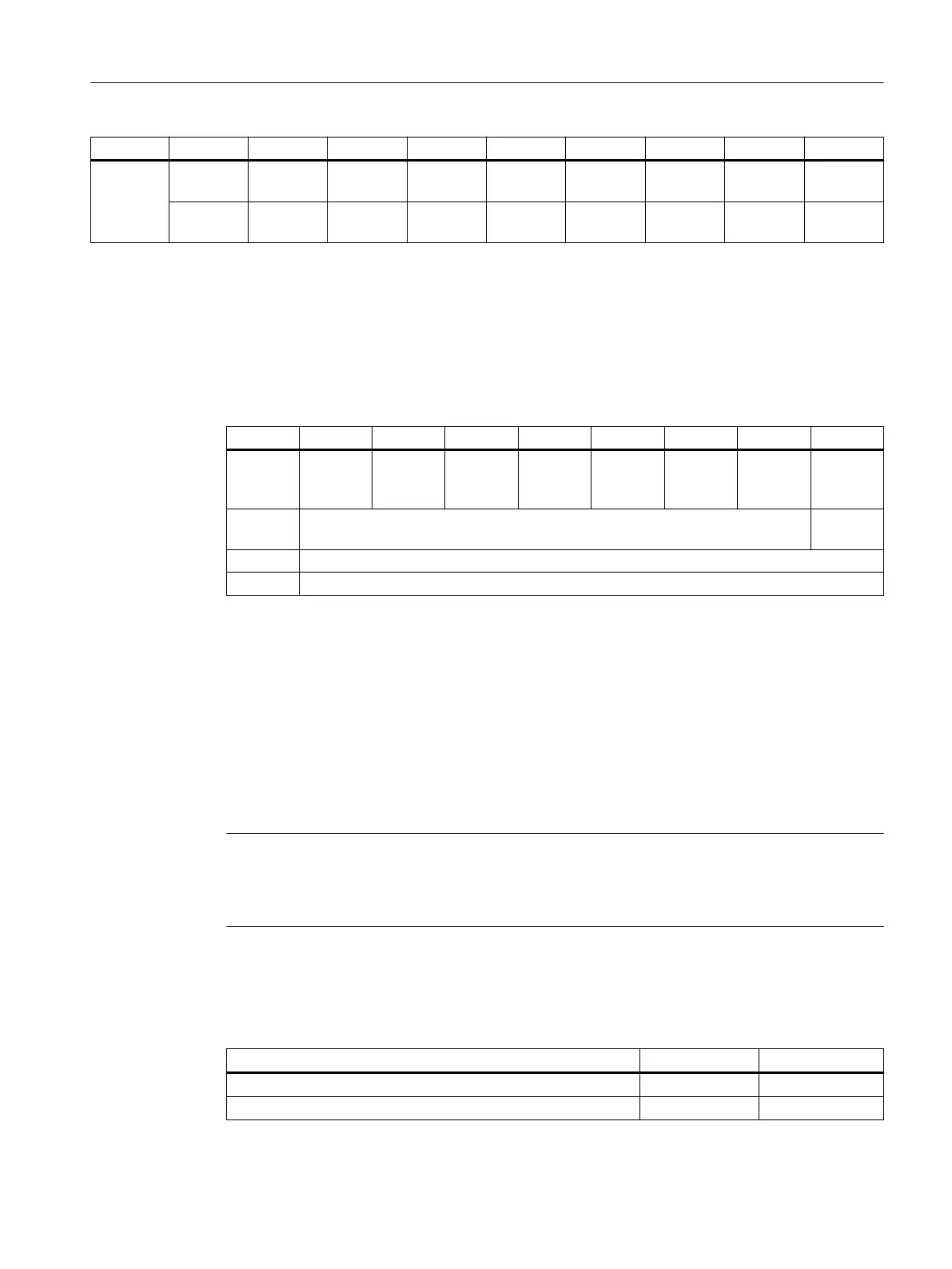
Parameters are assigned to the operating mode via the m+0 byte (Analog Control Byte 0) of the
output image of the analog outputs:
Byte Bit7 Bit6 Bit5 Bit4 Bit3 Bit3 Bit1 Bit0
m+0 AO
(channel
4)
AO
(channel
4)
AO
(channel
3)
AO
(channel
3)
AI
(channel
2)
AI
(channel
2)
AI
(channel
1)
AI
(channel
1)
m+1 Reserved Data for‐
mat
m+2 Reserved
m+3 Reserved
The reserved bits must be preassigned with the value "0".
The operating mode is set to "no operating mode" during ramp-up, as soon as a valid setting
is made this will be applied and will subsequently no longer be reset. If a reset is initiated by
the user, this is interpreted as an error.
Control type
The control type must be specied in the Analog Control Byte m+1 (bit 0), so that the 16-bit input
and output values from and to the analog module are correctly interpreted by the control. In the
SINUMERIK ONE control, the value "0" must be entered.
Note
The control type must be set prior to the operating mode so that the rst set of user data is not
misinterpreted. In addition to this, the Analog Control Byte m+0/m+1 must only be accessed
byte by byte.
Assigning parameters to the analog inputs
The analog inputs (AI) can be operated in the following operating modes:
Operating mode 1st channel Bit 1 Bit 0
No operating mode 0 0
Voltage measurement 0 1
Connectable components
12.2PP 72/48D PN and PP 72/48D 2/2A PN
NCU 1750
Equipment Manual, 10/2023, A5E45627807B AH 139
 Loading...


