12.2.3.2 Power supply
Requirements for the power supply
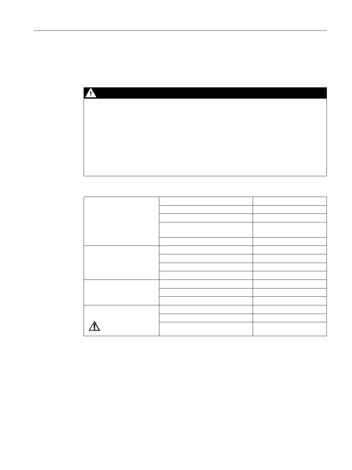
DANGER
Inadequately fused supply cables can be life-threatening
In the case of supply lines > 10 m, protectors must be installed at the device input in order to
protect against lightning (surge).
The DC power supply must be connected to the ground/shielding of the Control Unit for EMC
or functional reasons. For EMC reasons, this connection should only be made at one point. As
a rule, the connection is provided as standard in the PLC I/Os. If this is not the case in exceptional
circumstances, the ground connection should be made on the grounding rail of the control
cabinet.
See also: "EMC Installation Guideline" Conguration Manual
Rated voltage According to EN 61131-2 24VDC
Voltage range (average value) 20.4 V DC to 28.8 V DC
Voltage range (dynamic) 18.5 VDC to 30.2 V DC
Voltage ripple peak-to-peak 5% (unltered 6-pulse recti‐
cation)
Ramp-up time at POWER ON Any
Non-periodic overvoltages ≤ 35 V
Duration of overvoltage ≤ 500 ms
Recovery time ≥ 50 s
Events per hour ≤ 10
Transient voltage interrup‐
tions
Outage time ≤ 3 ms
Recovery time ≥ 10 s
Events per hour ≤ 10
X1 terminal Wiring area AWG 28 to AWG 12
Torque 0.51Nm
Conductor material Only use copper conductors
Digital inputs
The 24V supplied at X1 are used to supply the 72 digital inputs.
If the internal supply voltage is not used to supply the digital inputs, this can optionally be
replaced by an external power supply (24V DC). The reference ground of the power supply
source must each be connected with X111, X222, X333, pin 1 (GND). X111, X222, X333, pin
2 (P24OUT) then remains open.
Connectable components
12.2PP 72/48D PN and PP 72/48D 2/2A PN
NCU 1750
Equipment Manual, 10/2023, A5E45627807B AH 121
 Loading...


