The required 24V DC load power supply is wired to the screw-type terminal block (X1). Use
exible cables with a cross-section of 0.25 to 2.5mm
2
(or AWG 30 to AWG 12) for wiring the
power supply according to the maximum current that ows.
Note
If you only use one wire per connection, a ferrule is not required. You can use ferrules without
an insulating collar according to DIN46228, FormA long version.
Table 12-14 Requirements for digital inputs
Characteristics Value
Connection option Up to 2.5 mm2
Current carrying capacity Max. 10A
Maximum cable length 10 m
Digital outputs
To supply (24 V DC) the digital outputs, an additional external power supply source is required.
The power supply is connected to terminals X111, X222 and X333 via pins 47, 48, 49 and 50
(DOCOMx). Ground pins must be connected to a common chassis ground.
Maximum current consumption: 3 x 4A if all outputs are used simultaneously.
NOTICE
Protection against short-circuit
It is the user's responsibility to ensure that the max. current consumption per DOCOMx pin
(X111, X222, X333: pins 47, 48, 49, 50) does not exceed 1 A. The power supply (24 V DC) for
the digital outputs must therefore be connected to all 4 pins per DOCOMx (X111, X222, X333:
pins 47, 48, 49, 50).
Analog inputs/outputs
An additional external power supply is not required for the analog inputs and outputs.
Wiring the power supply
This interface is intended exclusively for the connection of the external 24 V power supply.
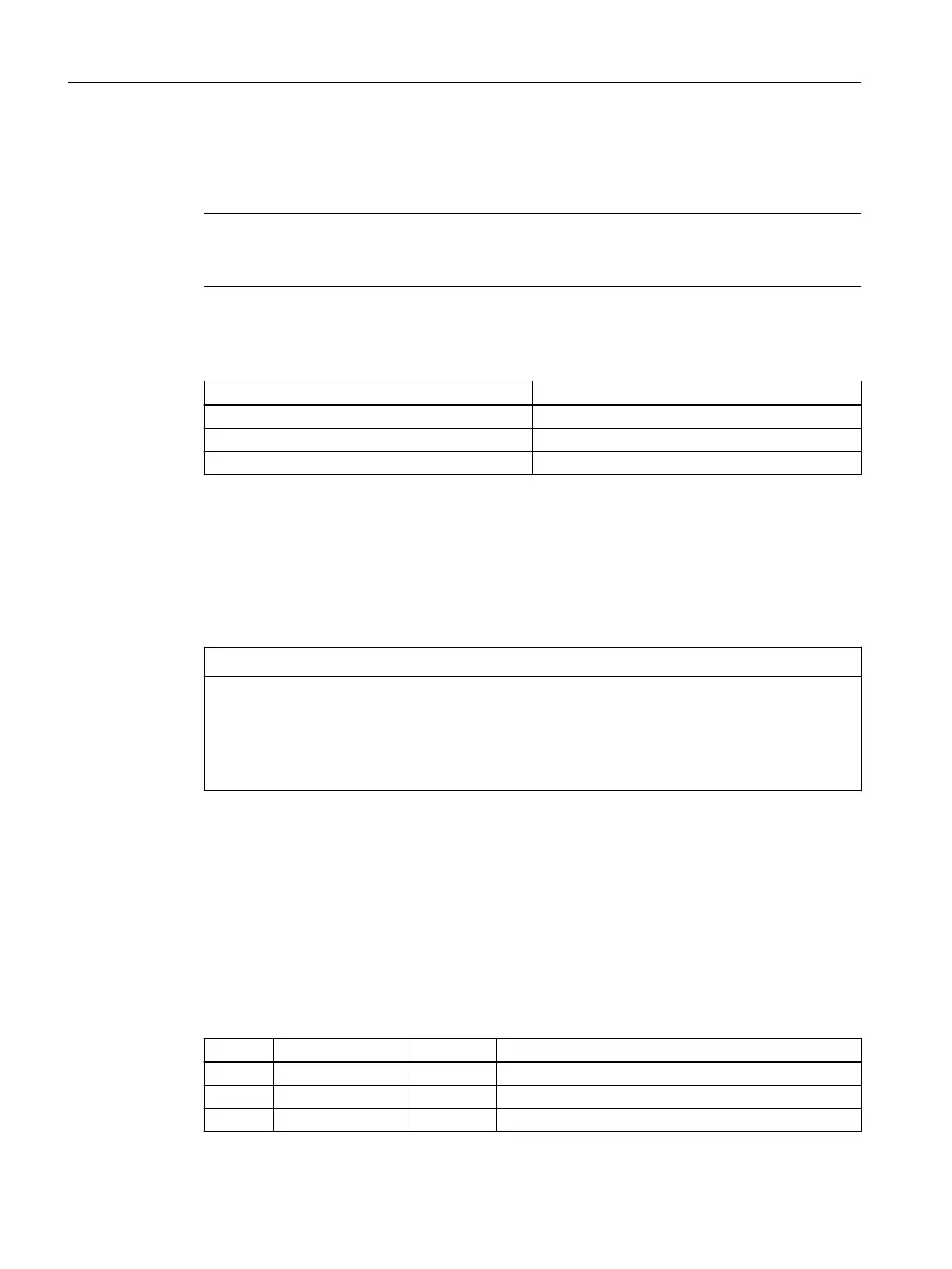
Table 12-15 Pin assignment at X1 screw-type terminal block
Pin Signal name Signal type Meaning
1 P24 VI 24VDC power supply
2 M GND Ground
3 PE GND Protective ground
Connectable components
12.2PP 72/48D PN and PP 72/48D 2/2A PN
NCU 1750
122 Equipment Manual, 10/2023, A5E45627807B AH
 Loading...


