• It is not possible to connect a 2-wire BERO.
• Power supply for digital inputs (X111, X222, X333: pin 2):
The internal power supply (P24OUT) is taken from the general power supply of module X1,
pin 2 (P24). Alternatively, an external power supply can be connected if the load at the digital
outputs becomes too high.
Table 12-26 Electrical specication of the digital inputs:
Digital inputs min. max. Nominal
High-level voltage (U
H
) 15 V 30 V 24 V
Input current I
IN
at V
H
2 mA 15 mA --
Low-level voltage (U
L
) -3 V + 5 V 0 V
Signal delay time T
PHL
0.5 ms 3 ms --
Signal delay time T
PHL
at X222: DI 3.0 to 3.7 -- -- 600 μs
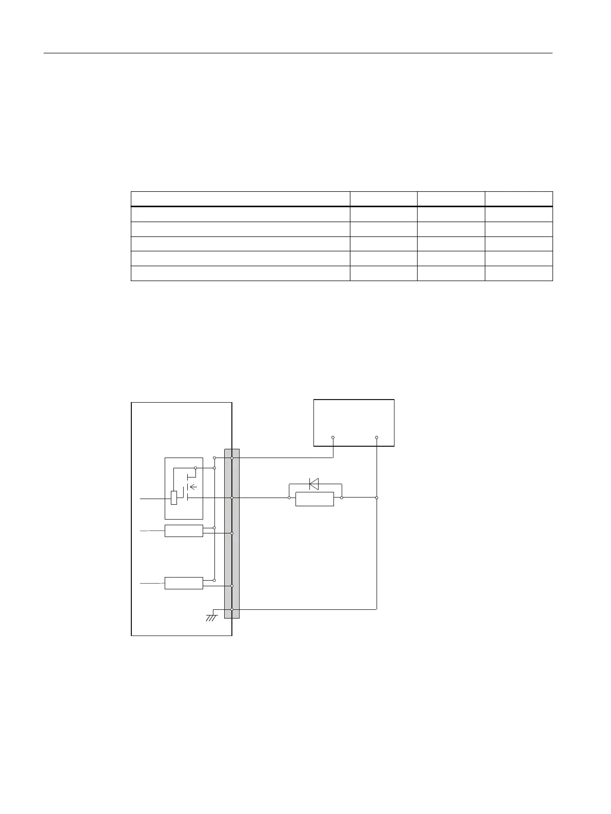
Specication of the digital outputs
Terminal assignment for the digital outputs
The following gure shows an example of the terminal assignment for the digital outputs on
connector X111. Connectors X222 and X333 are assigned analogously.
([WSRZHUVXSSO\
9'&VWDELOL]HG
;;;
3LQQXPEHU
'ULYHU
'ULYHU
'ULYHU
5HOD\
33'31
9
9
'2&20[
:
:
:
:
1 (M)
0
Characteristics
• No galvanic isolation.
• Protection against: Short-circuit, overtemperature, and loss of ground.
• Automatic disconnection in case of undervoltage.
Connectable components
12.2PP 72/48D PN and PP 72/48D 2/2A PN
NCU 1750
130 Equipment Manual, 10/2023, A5E45627807B AH
 Loading...


