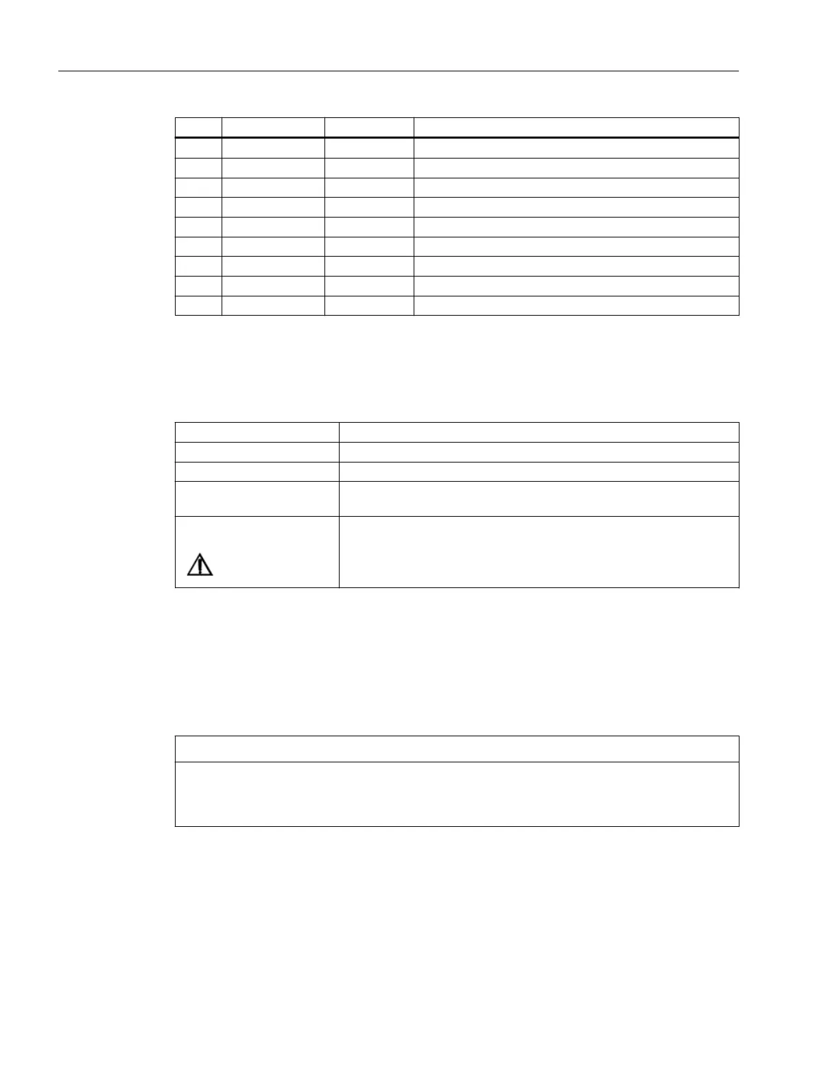
Pin Signal name Signal type Meaning
4 AI1- I Channel 1 analog input -
5 CO2 O Channel 2 current output for PT10
6 CI2 I Channel 2 current input for PT100
7 AI2+ I Channel 2 analog input +
8 AI2- I Channel 2 analog input -
9 AO3+ O Channel 3 current and voltage output +
10 AO3- O Channel 3 current and voltage output -
11 AO4+ O Channel 4 current and voltage output +
12 AO4- O Channel 4 current and voltage output -
AI: Analog input - AO: Analog output
CI: Current input - CO: Current output
Table 12-29 Cable specication:
Plug 12-pin socket/plug combination
Cable shielded
Max. cable length: 30 m
Max. connectable core cross-
section:
0.5 mm
2
Material for the cable Only use copper conductors. AWG 28 ~ AWG 24 (0.32 mm
2
~ 0.5 mm
2
).
Wiring analog inputs/outputs
Procedure:
1. Strip cable for analog signals.
2. Secure the stripped connection piece of the cable with the shield connection clamp.
NOTICE
Shielded signal cables for analog signals
To ensure safe, fault-free operation of the system, shielded cables with shield connection
should be used for the wiring of the analog outputs.
Connectable components
12.2PP 72/48D PN and PP 72/48D 2/2A PN
NCU 1750
132 Equipment Manual, 10/2023, A5E45627807B AH
 Loading...


