Note
If the DI/DQ interfaces X122, X132 and X142 are operated partially as DI and partially as DQ
(mixed operation), then the DI must be operated with the same power supply as the NCU
module power supply X124.
This applies to:
• 6FC5317-5AA00-0AA0, hardware versions FS: A to E
• 6FC5317-5AA00-0AA1, is not aected.
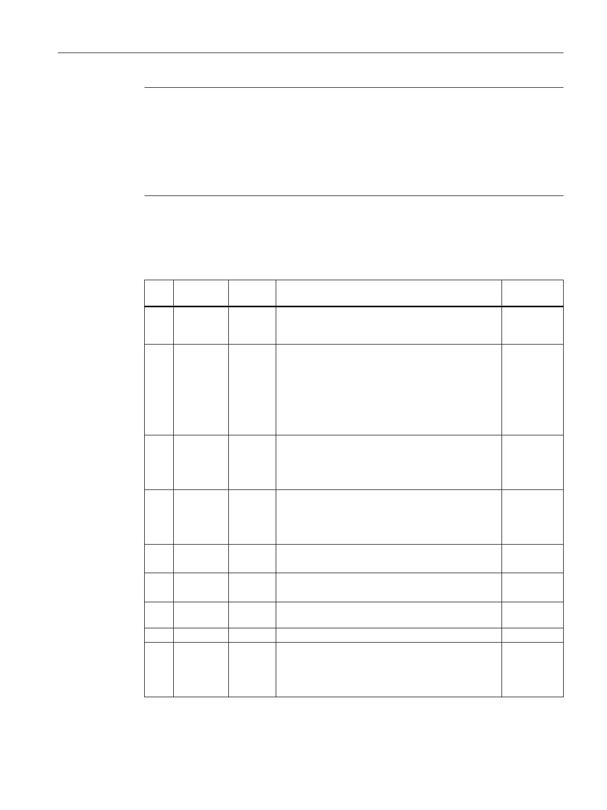
Pin assignment
Table 8-18 X122 digital inputs/outputs
Pin Signal
name
Signal
type
Meaning Default set‐
ting
1 DI0 I Digital input 0
Input ON/OFF1 infeed (if one infeed with a DRIVE-CLiQ
connection is operated at the NCU)
x
2 DI1 I Digital input 1
Input 2. Operating condition OFF3 drives
"OFF3 – rapid stop"
Braking with a congurable OFF3 ramp (p1135, p1136,
p1137); thereafter, pulse suppression and switching on
inhibited. The drive stops controlled. The braking re‐
sponse can be set separately for each SERVO.
x
3 DI2 I Digital input 2
Selection safe standstill group 1
SH/SBC - Group 1 SINAMICS Safety Integrated (SH =
p9601 release)
---
4 DI3 I Digital input 3
Selection safe standstill group 2
SH/SBC - Group 2 SINAMICS Safety Integrated (SH =
p9601 release)
---
5 DI16 I Digital input 16
Freely available
---
6 DI17 I Digital input 17
Freely available
---
7 G1 GND Ground for DI0 - DI3, DI16, DI17 (isolated with respect
to M)
8 M GND Ground for DI8 - DI11
9 DI/DO8 B Digital input/output 8 (rapid input)
Status safe standstill group 1
SH/SBC - Group 1
SINAMICS Safety Integrated
---
Connecting
8.10Digital inputs/outputs
NCU 1750
Equipment Manual, 10/2023, A5E45627807B AH 83
 Loading...


