Pin Signal
name
Signal
type
Meaning Default set‐
ting
9 IN/OUT4 B Digital NC output 1 $A_OUT[1] xed
10 IN/OUT5 B Digital NC output 2 $A_OUT[2] xed
11 M GND Ground for I0 - I7 ---
12 IN/OUT6 B Digital NC output 3 $A_OUT[3] xed
13 IN/OUT7 B Digital NC output 4 $A_OUT[4] xed
14 M GND Ground for I0 - I7 ---
Signal type: B = Bidirectional; GND = reference potential (ground)
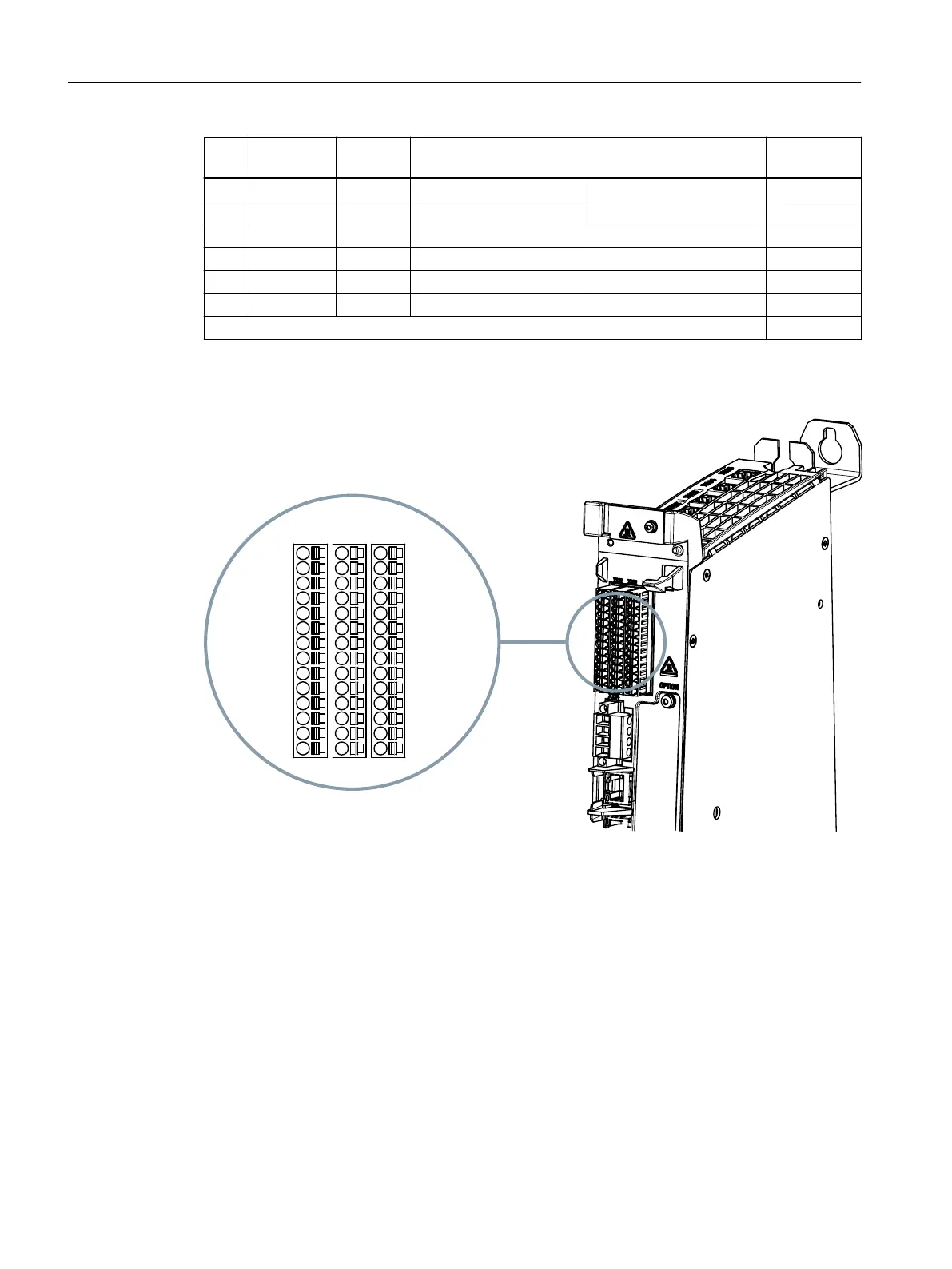
Position of connectors
Figure8-8 Digital inputs/outputs (interfaces X122, X132 and X142)
Connecting
8.10Digital inputs/outputs
NCU 1750
86 Equipment Manual, 10/2023, A5E45627807B AH
 Loading...


