2 Functions
66
7UT613/63x Manual
C53000-G1176-C160-2
Please observe the definition of the sides which you have performed during setting of
the topology of the main protected object (cf. Determining the Topology). Generally,
side 1 is the reference winding having a current phase angle of 0° and no vector group
indicator. Usually this is the higher voltage winding of the transformer.
The object data contain information about each of the sides of the protected object as
defined in the topology statements. No data of the sides which are not assigned are
requested here. They will be entered at a later date (margin heading „Object Data for
Further Protected Objects“).
For side 1
the device needs the following information:
• The primary rated voltage U
N
in kV (phase-to-phase) under address 311 UN-PRI
SIDE 1.
• The primary rated apparent power under address 312 SN SIDE 1. Note that the
power ratings of the windings of power transformers with more than 2 windings may
differ. Here, the rating of the winding assigned to side 1 is decisive. The power must
always be entered as a primary value, even if the device is generally configured in
secondary values. The device calculates the rated current of the protected winding
from this power.
• The starpoint condition under address 313 STARPNT SIDE 1: Earthed or
Isolated. If the starpoint is earthed via a current-limiting circuit (e.g. low-resistive)
or via a Petersen-coil (high-reactive), set Earthed, too. The starpoint is also
treated as Earthed if a starpoint former (neutral earthing reactor) is installed within
the protected zone of the winding.
• The mode of interconnection of the transformer windings under address 314
CONNECTION S1. If side 1 is that of the high-voltage side of the transformer, this is
normally the capital letter of the vector group according to IEC (Y or D). For auto-
transformers and single-phase transformers, only Y is permitted.
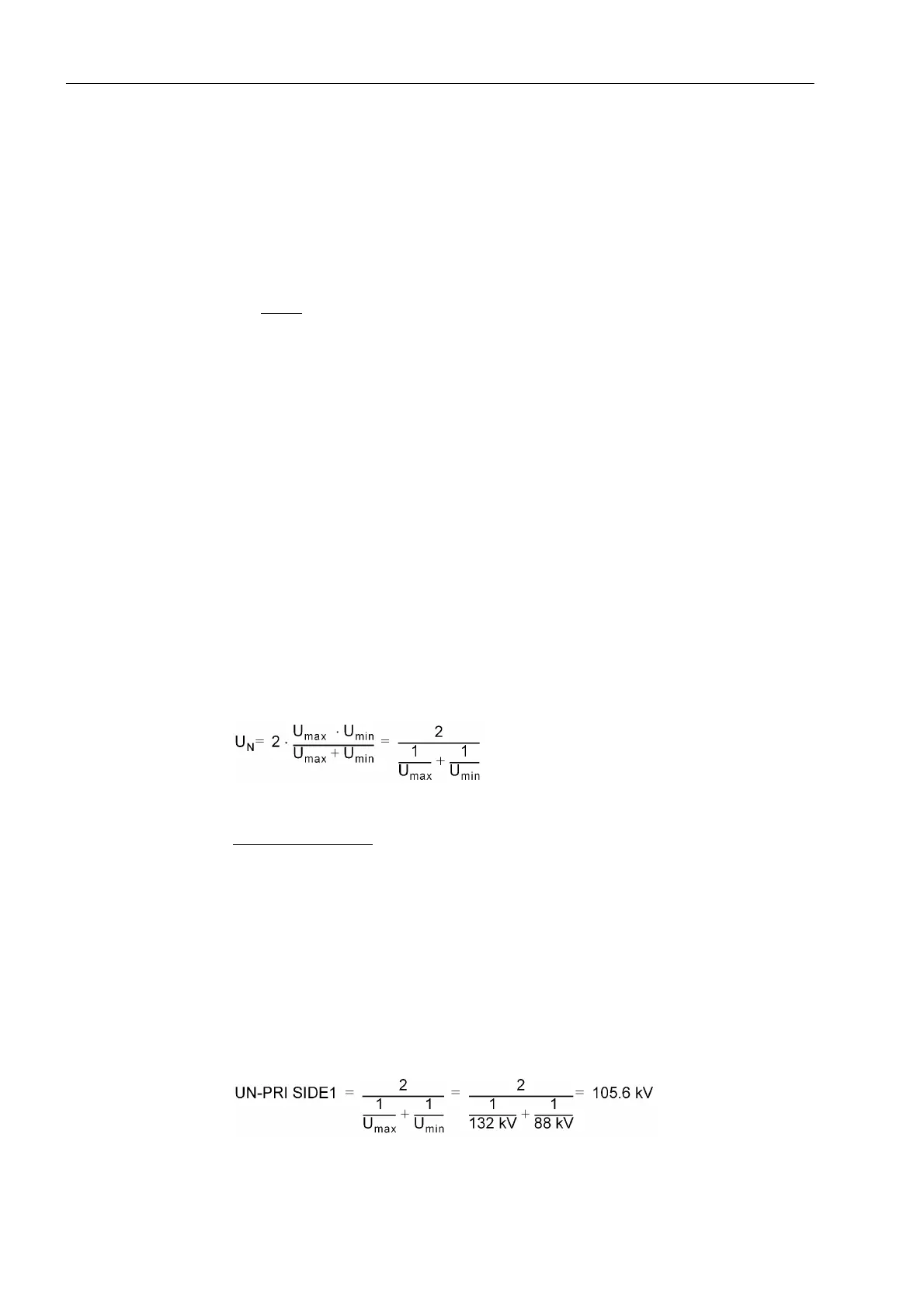
If the transformer winding is regulated, not the actual rated voltage of the winding U
NB
is used, but rather the voltage which corresponds to the average current of the regu-
lated range.
with U
max
, U
min
at the limits of the tap changer.
Calculation example
:
Transformer YNd5
35 MVA
110 kV/20 kV
Y–winding with tap changer ±20 %
This results for the regulated winding (110 kV) in:
maximum voltage U
max
= 132 kV
minimum voltage U
min
= 88 kV
Voltage setting (address 311)
 Loading...


