SIRIUS 3RT2 contactors/contactor assemblies
2.4 Configuration
SIRIUS Innovations
140 System Manual, 01/2011, A8E56203870002-03
φ = switchover current factor = switchover current peak/starting current peak
The switchover current factor has a theoretical maximum value of 2.
Example measurements:
Favorable circuit: φ = 0.8
Unfavorable circuit: φ = 1.37
Note
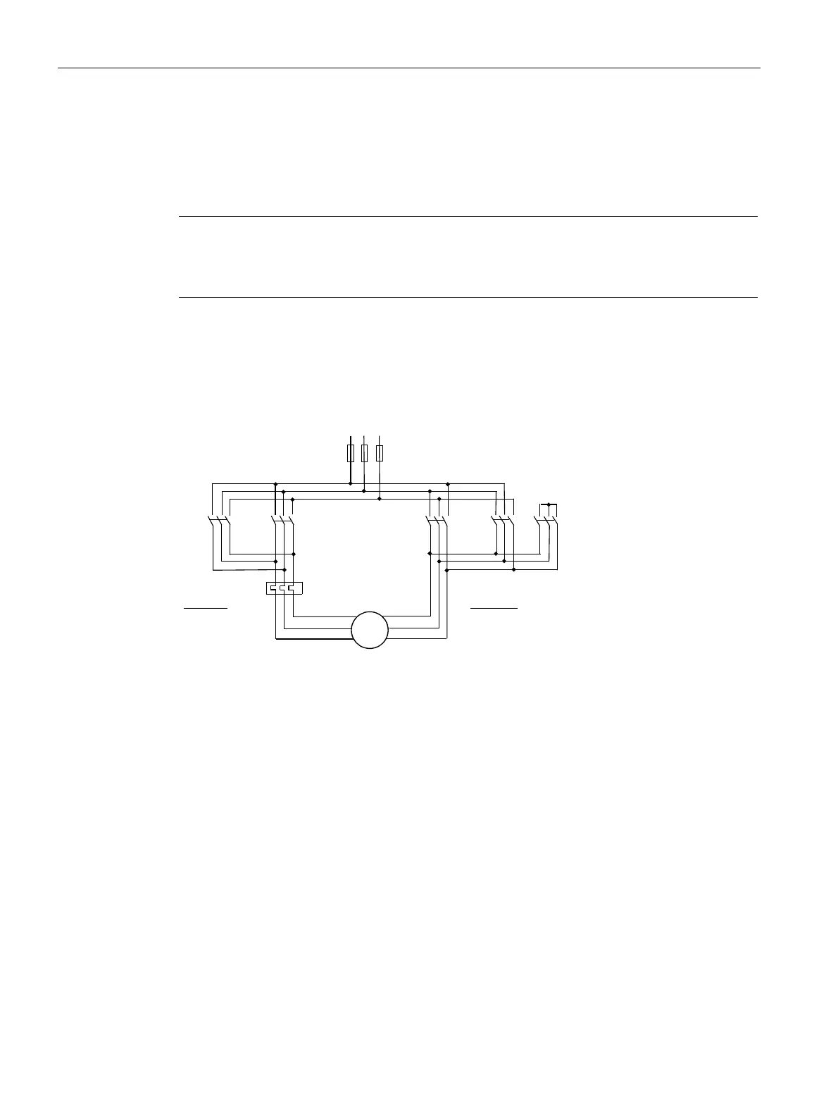
See the main and control circuit wiring designs below; these depict the circuit diagrams for
contactor assemblies for star-delta (wye-delta) start with clockwise and counterclockwise
rotation according to the preferred wiring.
Main circuit
The diagram below shows the preferred main circuit wiring for a star-delta circuit, clockwise
and counterclockwise rotation.
/LQH
&&:
/LQH
&:
&&:URWDWLRQ
&:URWDWLRQ
'HOWD
&:
'HOWD
&&:
0
ɫ
a
:
:
9
9
8
8
/99/
/88/
/::/
/88/
/99/
/::/
///
<
Figure 2-16 Main circuit of the contactor assembly for star-delta (wye-delta) start
 Loading...


