System overview
1.9 Connection
SIRIUS Innovations
84 System Manual, 01/2011, A8E56203870002-03
1.9.2.3 Conductor cross-sections for ring cable lug connection system
Conductor cross-sections for ring cable lug connection system
The tables below define the permissible conductor cross-sections for main terminals and
auxiliary conductor connections in sizes S00 and S0 for ring cable lug connection systems.
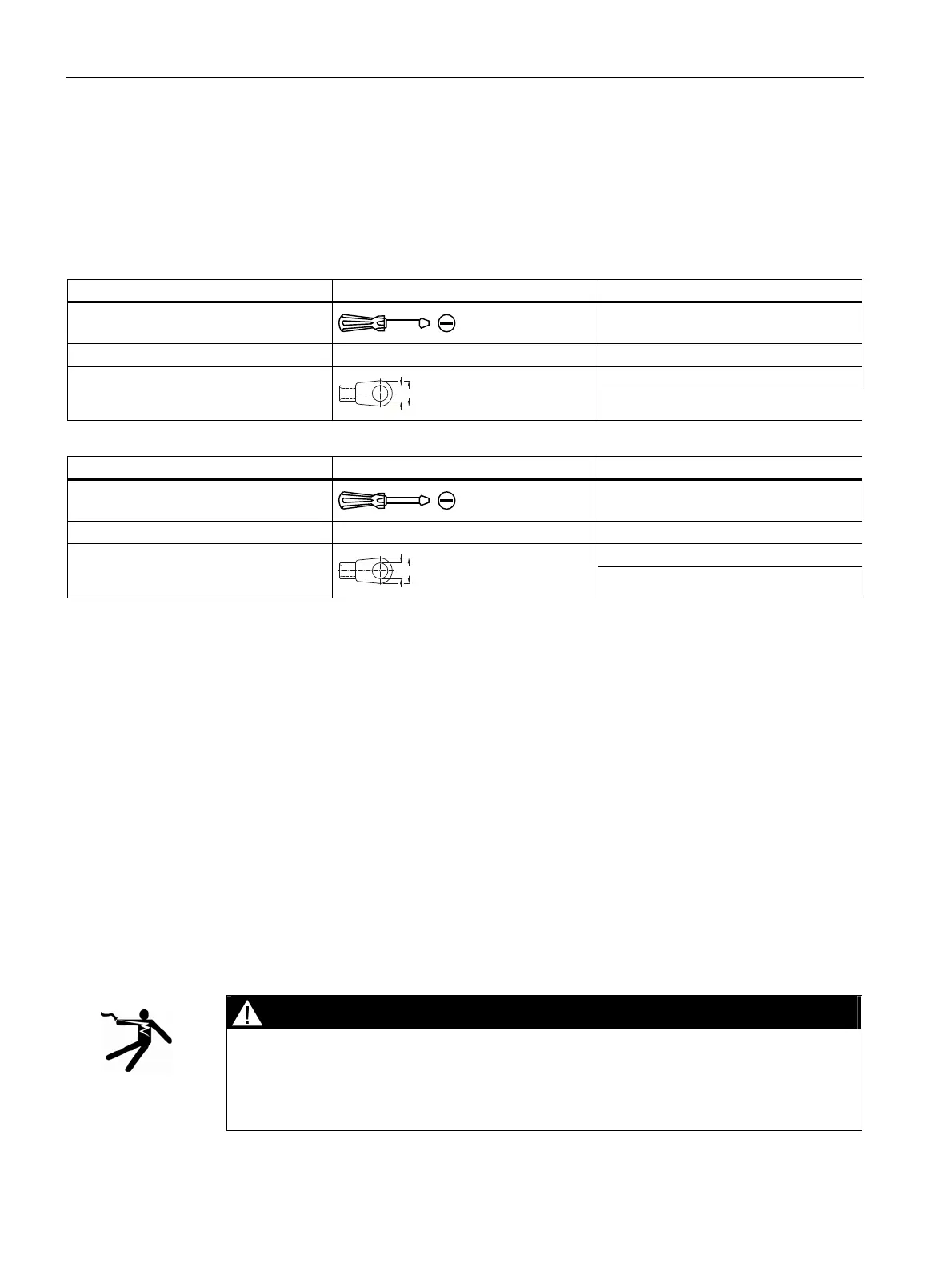
Table 1- 34 Main conductors and auxiliary conductors of size S00 with M3 combination screws
SIRIUS devices
Tool
Pozidriv size 2,
Ø 5 to 6 mm
Tightening torque 0.8 to 1.2 Nm
d
2
= min. 3.2 mm Ring cable lug
1)
d
2
d
3
d
3
= max. 7.5 mm
Table 1- 35 Main conductors and auxiliary conductors of size S0 with M4 combination screws
SIRIUS devices
Tool
Pozidriv size 2,
Ø 5 to 6 mm
Tightening torque 2.0 to 2.5 Nm
d
2
= min. 4.3 mm Ring cable lug
1)
d
2
d
3
d
3
= max. 12.2 mm
1)
The following ring cable lugs are approved for achieving the required clearances and creepage distances:
● For applications according to IEC 60947-1:
– DIN 46237 (with insulating sleeve)
– JIS CS805 type RAV (with insulating sleeve)
– JIS CS805 type RAP (with insulating sleeve)
● For applications according to UL 508:
– DIN 46 234 (without insulating sleeve)
– DIN 46225 (without insulating sleeve)
– JIS CS805 (without insulating sleeve)
A shrink-on sleeve must be used to insulate ring cable lugs without an insulating sleeve. The following
conditions must be met:
● Application temperature: -55 °C to +155 °C
● UL 224 approved
● Flame-protected
DANGER
Hazardous voltage.
Will cause death or serious injury.
Only use approved ring cable lugs to meet the required clearances and creepage
distances.
 Loading...


