System overview
1.9 Connection
SIRIUS Innovations
82 System Manual, 01/2011, A8E56203870002-03
1.9.2.2 Conductor cross-sections for spring-loaded connection systems
Conductor cross-sections for spring-loaded connection systems
The tables below define the permissible conductor cross-sections for main terminals and
auxiliary conductor connections in sizes S00 and S0 for spring-loaded connection systems.
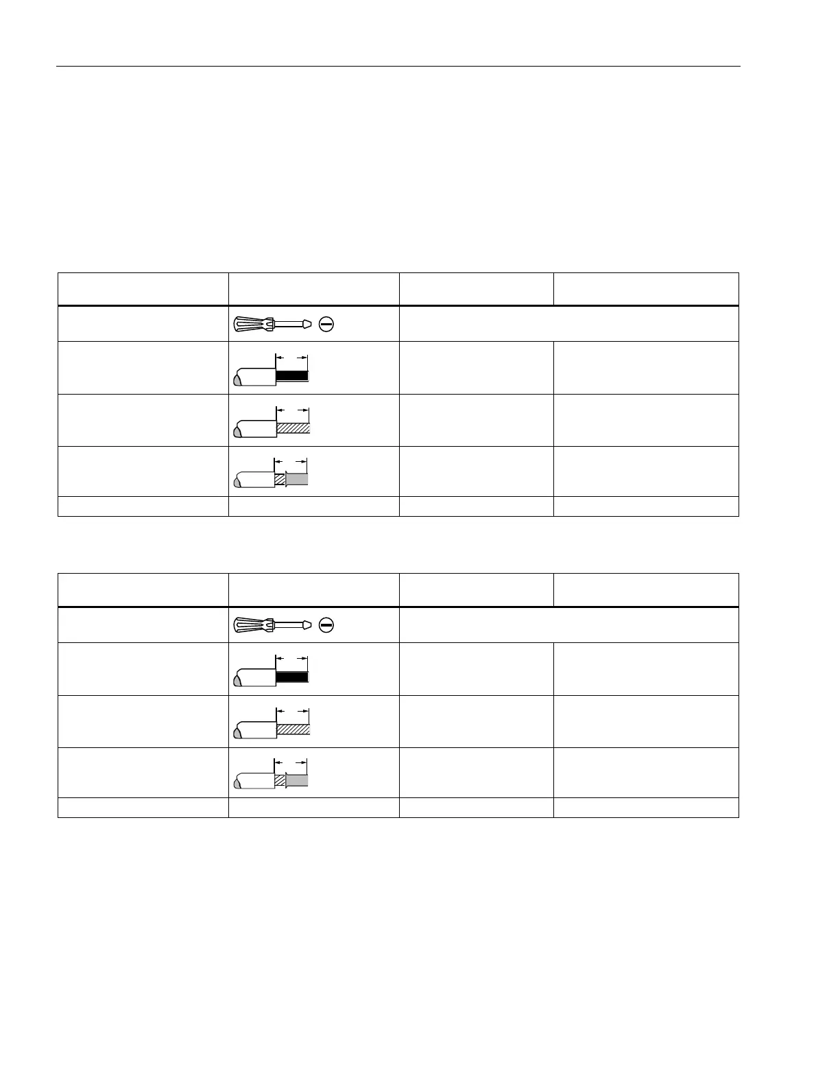
Table 1- 30 Main conductors of size S00
Motor starter protectors,
contactors
Overload relays,
current monitoring relays
Tool
Ø 3.5 x 0.5 (8WA2880/8WA2803)
Ø 3.0 x 0.5 (3RA2808-1A)
Solid and stranded
2 x (0.5 to 4.0) mm² 0.5 to 4.0 mm²
Finely stranded without end
sleeve
2 x (0.5 to 2.5) mm² 0.5 to 2.5 mm²
Finely stranded with end
sleeve (DIN 46228 Part 1)
2 x (0.5 to 2.5) mm² 0.5 to 2.5 mm²
AWG 2 x (20 to 12) 2 x (20 to 12)
Table 1- 31 Main conductors of size S0
Motor starter protectors,
contactors
Overload relays,
current monitoring relays
Tool
Ø 3.5 x 0.5 (8WA2880/8WA2803)
Ø 3.0 x 0.5 (3RA2808-1A)
Solid and stranded
2 x (1.0 to 10) mm² 1.0 to 10 mm²
Finely stranded without end
sleeve
2 x (1.0 to 6.0) mm² 1.0 to 6.0 mm²
Finely stranded with end
sleeve (DIN 46228 Part 1)
2 x (1.0 to 6.0) mm² 1.0 to 6.0 mm²
AWG 2 x (18 to 8) 2 x (18 to 8)
 Loading...