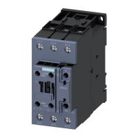
SIRIUS 3RT2 contactors/contactor assemblies
2.8 Technical data
SIRIUS Innovations
System Manual, 01/2011, A8E56203870002-03
279
2.8.5 Accessories for 3RT2 contactors and 3RH2 contactor relays
2.8.5.1 General data - Pneumatic timer 3RT2926-2P.
Table 2- 119 General data for the pneumatic delay block 3RT2926-2P.
Type 3RT2926-2P.
Pneumatic delay block
1)
General data
Mechanical durability Operating
cycles
5 million
Electrical durability at I
e
Operating
cycles
1 million
Rated insulation voltage U
i
(pollution degree 3) V 690
Operation
°C -25 … + 60
Permissible ambient temperature
Storage
°C -50 … + 80
Rated operational currents I
e
acc. to DIN EN 60947 utilization
categories
AC 12
A 10
Up to 230/220 V A 6
400/380 V A 4
500 V A 2.5
AC 15/AC 14 at U
e
690/660 V A 1.5
24 V A 4
48 V A 2
110 V A 0.7
220 V A 0.3
DC 13 at U
e
440 V A 0.15
Conductor cross-sections
Solid, stranded
mm
2
2 x (0.5 to 2.5)
2)
or 2 x (2.5 to 4)
2)
Finely stranded with end sleeve
mm
2
2 x (0.5 to 2.5)
AWG cables
AWG 2 x (22 to 14)
Tightening torque of connection screws
Nm 0.8 to 1.1
Time delay
Accuracy
± 10 %
CSA and UL rated data
Rated voltage
V AC 600
Switching capacity
A 600, Q 600
1)
For size S0. No other auxiliary switch blocks are permitted in addition to the pneumatic delay block.
2)
If two different conductor cross-sections are connected to one clamping point, both cross-sections must be located in
the range specified. If identical cross-sections are used, this restriction does not apply.

 Loading...


