System overview
1.9 Connection
SIRIUS Innovations
80 System Manual, 01/2011, A8E56203870002-03
1.9.2.1 Conductor cross-sections for screw-type connection systems
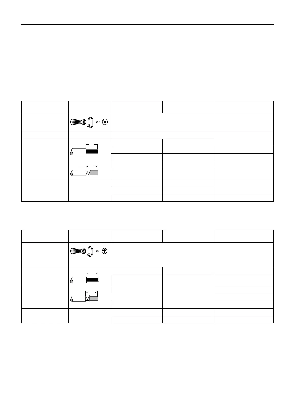
Conductor cross-sections for screw-type connection systems
The tables below define the permissible conductor cross-sections for main terminals and
auxiliary conductor connections in sizes S00 and S0 for screw-type connection systems.
Table 1- 26 Main conductors of size S00 with M3 combination screws
Motor starter protectors Contactors Overload relays
1)
,
current monitoring relays
1)
Tool
Pozidriv size PZ 2, Ø 5 to 6 mm
Tightening torque 0.8 to 1.2 Nm
2 x (0.5 to 1.5) mm² 2 x (0.5 to 1.5) mm²
2 x (0.75 to 2.5) mm² 2 x (0.75 to 2.5) mm² 2 x (0.75 to 2.5) mm²
Solid and stranded
Max. 2 x 4 mm² Max. 2 x 4 mm² Max. 2 x 4 mm²
2 x (0.5 to 1.5) mm² 2 x (0.5 to 1.5) mm² 2 x (0.5 to 1.5) mm² Finely stranded with
end sleeve
DIN 46228 Part 1
2 x (0.75 to 2.5) mm² 2 x (0.75 to 2.5) mm² 2 x (0.75 to 2.5) mm²
2 x (20 to 16) 2 x (20 to 16)
2 x (18 to 14) 2 x (18 to 14) 2 x (18 to 14)
AWG
2 x 12 2 x 12 2 x 12
1)
Only 1 conductor can be clamped on the stand-alone assembly support.
Table 1- 27 Main conductors of size S0 with M4 combination screws
Motor starter protectors Contactors Overload relays
1)
,
current monitoring relays
1)
Tool
Pozidriv size PZ 2, Ø 5 to 6 mm
Tightening torque 2.0 to 2.5 Nm
2 x (1.0 to 2.5) mm² 2 x (1.0 to 2.5) mm² 2 x (1.0 to 2.5) mm² Solid and stranded
2 x (2.5 to 10) mm² 2 x (2.5 to 10) mm² 2 x (2.5 to 10) mm²
2 x (1 to 2.5) mm² 2 x (1 to 2.5) mm² 2 x (1 to 2.5) mm²
2 x (2.5 to 6) mm² 2 x (2.5 to 6) mm² 2 x (2.5 to 6) mm²
Finely stranded with
end sleeve
DIN 46228 Part 1
Max. 1 x 10 mm² Max. 1 x 10 mm² Max. 1 x 10 mm²
2 x (16 to 12) 2 x (16 to 12) 2 x (16 to 12) AWG
2 x (14 to 8) 2 x (14 to 8) 2 x (14 to 8)
1)
Only 1 conductor can be clamped on the stand-alone assembly support.
 Loading...


