System configuration
6.3 System configuration rules
3SK1 safety relays
Manual, 04/2013, A5E02526190021A/RS-AA/01
101
● If an output expansion is not detected on powering up, the internal feedback circuit will
not be evaluated.
● In the case of a change to the device configuration during operation, error mode is
activated immediately. A restart can only take place via a Power OFF/ON.
All other configuration changes during operation are indicated by LED (DEVICE LED
flashes green/yellow).
See also
Accessories (Page 257)
Configuration notes for using device connectors
Device connectors 3ZY12 can only be used with devices of the Advanced device series.
Further configuration notes:
NOTICE
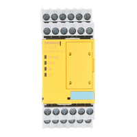
Only one 3SK1 Advanced basic unit is permitted per system
The safety function is not guaranteed when more than one basic unit is used.
NOTICE
Supply voltage must only be fed in on the basic unit
The supply voltage of 24 V DC must only be fed in on the basic unit, otherwise the safety
function is bypassed.
Power supply
● When device connectors are used, only one 3SK1230 power supply is permitted per
system.
● The 3SK1230 power supply must always be located on the extreme left.
● If the 3SK1230 power supply is used, an additional (external) 24 V DC connection is not
permitted (this also applies for the cascading input, as well as for non-floating sensors).
24 V DC power supply
● It is only permitted to connect a voltage of 24 V DC to the terminals on the basic unit.
● It is not permitted to supply 24 V DC to an expansion component.

 Loading...

