44
SIVACON S8 Planning Principles – Universal mounting design
shutters are opened automatically when the withdrawable
unit is inserted into the compartment.
Connection is effected in a separate cable connection
compartment. The connection data for main circuits are
stated in Tab. 4/14, those for auxiliary circuits in Tab. 4/15
and the number of available auxiliary contacts in Tab. 4/16.
The rated current for auxiliary contacts is:
• 6 A (250 V) for small withdrawable units
• 10 A (250 V) for normal withdrawable units
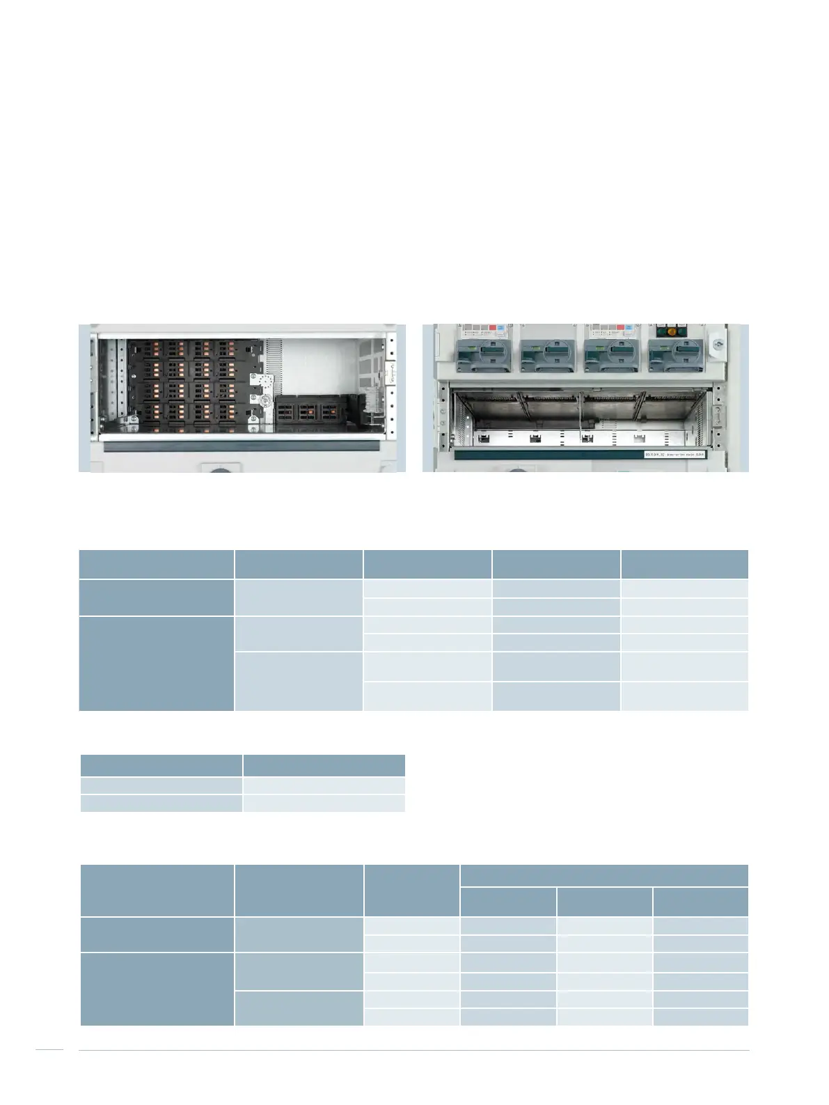
4.3.4 Withdrawable unit compartment in
HFD
The vertical distribution busbar is covered test finger
proofed (IP2X). Phase separation is possible. No connection
work is required in the compartment (Fig. 4/14). The
internal separation options up to form 4b lead to a high
degree of personal safety.
For small withdrawable units, an adapter plate is mounted
at the top of the compartment (Fig. 4/15). The tap-off
openings for the input contacts of the withdrawable units
in the compartment can be equipped with shutters. The
Tab. 4/14: Connection data for the main circuit
Withdrawable unit
height
Nominal feeder current Terminal size
Maximum connection
cross section
Small withdrawable unit
150 mm, 200 mm
≤ 35 A 16 mm
2
-
≤ 63 A 35 mm
2
-
Normal withdrawable unit
100 mm
≤ 35 A 16 mm
2
-
≤ 63 A 35 mm
2
-
≥ 150 mm
≤ 250 A -
1 x 185 mm
2
2 x 120 mm
2
> 250 A -
2 x 240 mm
2
4 x 120 mm
2
Tab. 4/15: Connection data for the auxiliary circuit
Fig. 4/14: Compartment for normal withdrawable unit in HFD
Withdrawable unit
height
Control plug type
Number of available auxiliary contacts
Without
communication
With PROFIBUS With PROFINET
Small withdrawable unit
150, 200 mm
26-pole 26 20 19
40-pole 40 37 32
Normal withdrawable unit
≥ 100 mm
12-pole 12 9 12
24-pole 24 21 24
≥ 150 mm
32-pole 32 29 32
40-pole 40 37 40
Tab. 4/16: Number of available auxiliary contacts for withdrawable
units in HFD
Type Terminal size
Push-in terminal connection 2.5 mm
2
Screw connection 2.5 mm
2
Fig. 4/15: Adapter plate for small withdrawable units

 Loading...


