3BHARDWARE CONFIGURATION AND INSTALLATION
Terminal Signal name Remarks
8 SENSE2+ Channel 2: sensor line +
9 SENSE2- Channel 2: sensor line -
10 SIG2+ Channel 2: measuring line +
11 SIG2- Channel 2: measuring line -
12 EXC2+ Channel 2: load cells supply voltage +
13 EXC2- Channel 2: load cells supply voltage -
Table 4-4 Connection of load cells channel 2
The following rules are to be observed when connecting load cells (LC):
1. The use of a junction box (JB) becomes necessary when more than one LC is
connected (the LCs must be connected in parallel).
2. If the distance between the LC and SIWAREX U is larger than the obtainable
length of the LC connection cable, then you must use extension box (EB).
3. The cable shield is normally run on the cable guide supports of the junction box.
Where there is a danger of potential equalization currents via the cable shield, a
potential equalization conductor is to be laid parallel to the load cell cable or the
shield clamp in the JB is to be used for the shield support. Using the potential
equalization conductor is a preferable method as regards EMC (electromagnetic
compatibility).
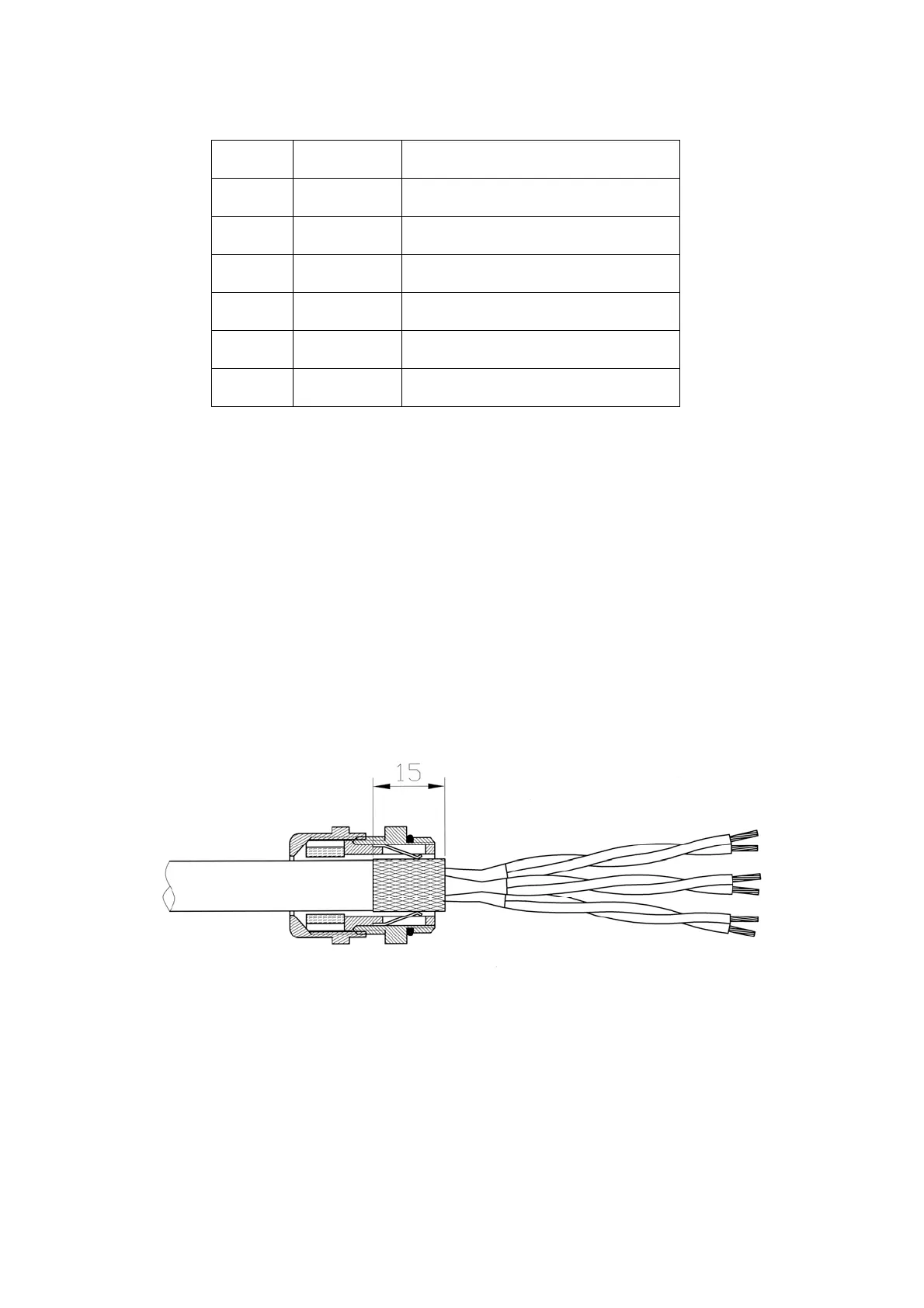
Figure 4-3 Shielding in the screw joint
3. Twisted pairs of conductors are necessary for the specified lines:
- Sensor line (+) and (-)
SIWAREX U 4-17