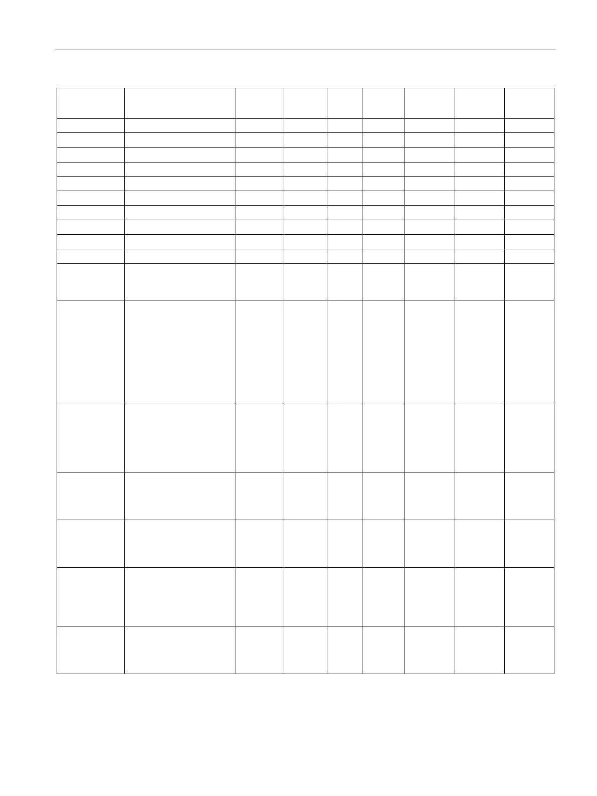
Scale parameters and functions
8.8 DR 7 Process interfaces
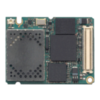
SIWAREX WP251
Manual, 12/2015, A5E37203357A
89
Bit 7 Reserve BIT 0 rw 0 0 1 1314.9
Analog output
range
0: 0 … 20 mA
1: 4 … 20 mA
USHORT 2 rw 0 0 1 1315
Analog output
source
(Page 93)
Basis of analog value
output:
0 = G/N value
1 = Gross
2 = Net
3 = Ext. specification,
DR 17
4 = Ext. specification, S7
USHORT 2 rw 2 0 3 1316
Response of
analog output
to faults or
SIMATIC
STOP
0: Switch off
1: Continue
2: Output configured
output value
3: Output maximum value
USHORT 2 rw 0 0 3 1317
Start value for
the analog
output
Value at which 0 …4 mA
is to be output
FLOAT 4 rw 0 maximum
weighing
range
maximum
weighing
range
1318
End value for
the analog
output
Value at which 20 mA is
to be output
FLOAT 4 rw 0 maximum
weighing
range
maximum
weighing
range
1320
Output value
following fault
or SIMATIC
STOP
Value to be output when
the OutDis signal is ena-
bled (in mA)
FLOAT 4 rw 0 0 24 1322
Trace record-
ing cycle
(Page 94)
1: 10 ms
10: 100 ms
100: 1 s
USHORT 2 rw 1 1 1000 1324