Overview
16
Building Technologies A6V10257473_e_en_--
Fire Safety 2015-03-04
4.5 XCM1002
32
2411
12
13
14
15
16
17
18
19
20
21
22
23
25
26
27
28
29
30
31
10
7
1
2
3
5
6
8
9
4
X23
X24
ON
12
X8
X3X4
X28
X1
F3
F6 F5 F4
F2 F1
X14 X15 X16 X17
X13
X18
X26
S1
X21
1
X11
1
X12
X10X27 1X9
1
X7X6
11
X5 11
1
S18
X35
X20
41 2 3
5
6
7
8
9
10
11
12
13
14
15
1
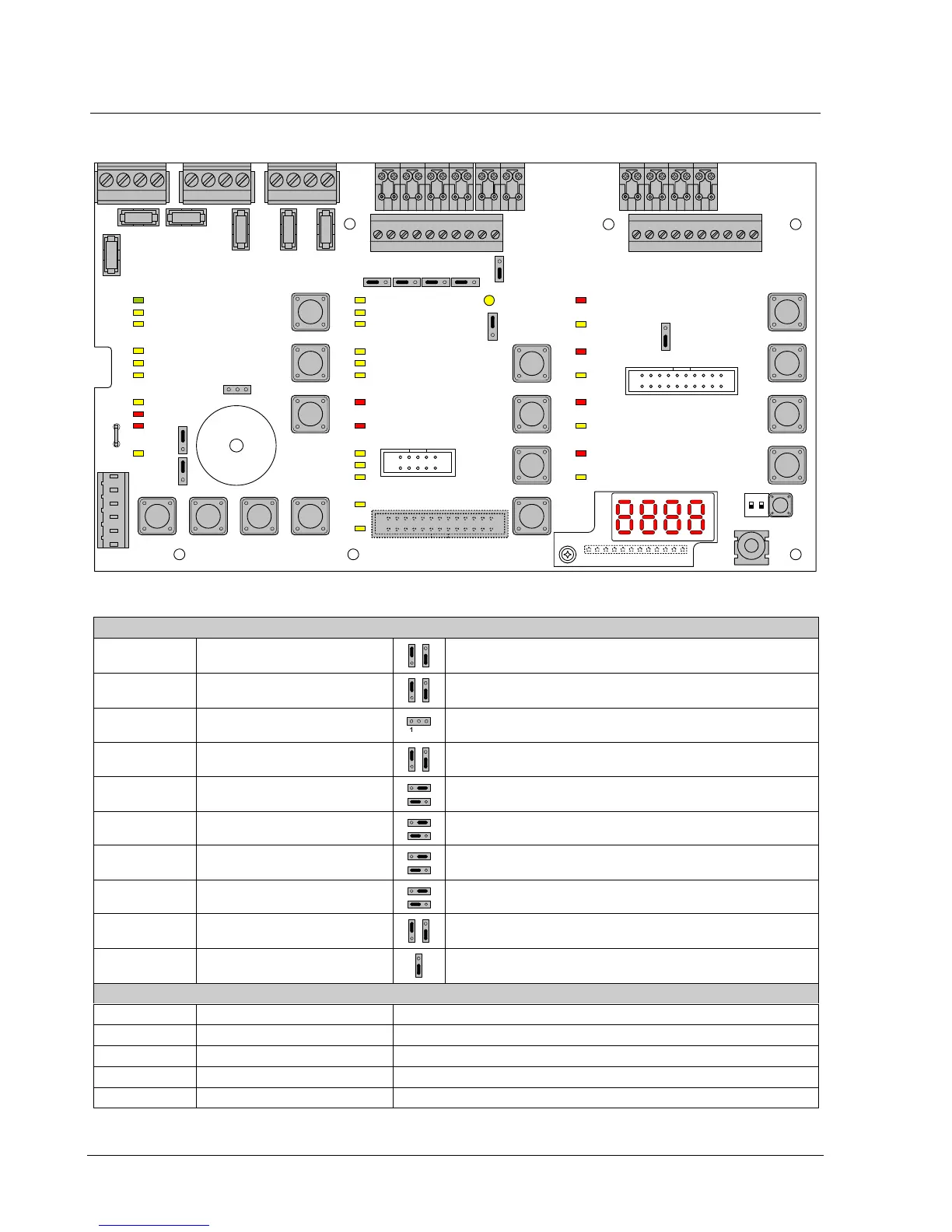
Fig. 5 XCM1002 board
Setting elements
X3 Internal buzzer Enable/Disable Jumper up (factory setting) : buzzer enabled
Jumper down : buzzer disabled (only for servicing)
X4 Type of power supply Jumper up (factory setting) : FCP1004-E
Jumper down : do not use (for further use of external power supply)
X8 Operating access Level 2 Jumper on the left: Level 2 permanent access
1 – 2: external key switch (option)
X13 Relay contact type 1
(NO or NC)
Jumper up : NC contact
Jumper down (factory setting) : NO contact
X14 Relay contact type 5
(NO or NC)
Jumper on the right : NC contact
Jumper on the left (factory setting) : NO contact
X15 Relay contact type 4
(NO or NC)
Jumper on the right : NC contact
Jumper on the left (factory setting) : NO contact
X16 Relay contact type 3
(NO or NC)
Jumper on the right : NC contact
Jumper on the left (factory setting) : NO contact
X17 Relay contact type 2
(NO or NC)
Jumper on the right : NC contact
Jumper on the left (factory setting) : NO contact
X18 Repeater (RTNet end of line
element)
Jumper up (factory setting) : EOL connected
Jumper down : do not use
X26 Serial connection (not used) Jumper down (factory setting) : do not change the position
Other elements
F1 / F2 Pluggable fuse 2 AF Fuse for protection of control outputs 4 (F1) and 5 (F2)
F3 Pluggable fuse 1 AT Fuse for protection of 24V output
F4 / F5 / F6 Pluggable fuse 1 AT Fuse for protection of control outputs 1 (F4), 2 (F5) and 3 (F6)
S1 Reset —
S18-1 / S18-2 Not used Do not change (factory setting : OFF)
 Loading...


