Overview
18
Building Technologies A6V10257473_e_en_--
Fire Safety 2015-03-04
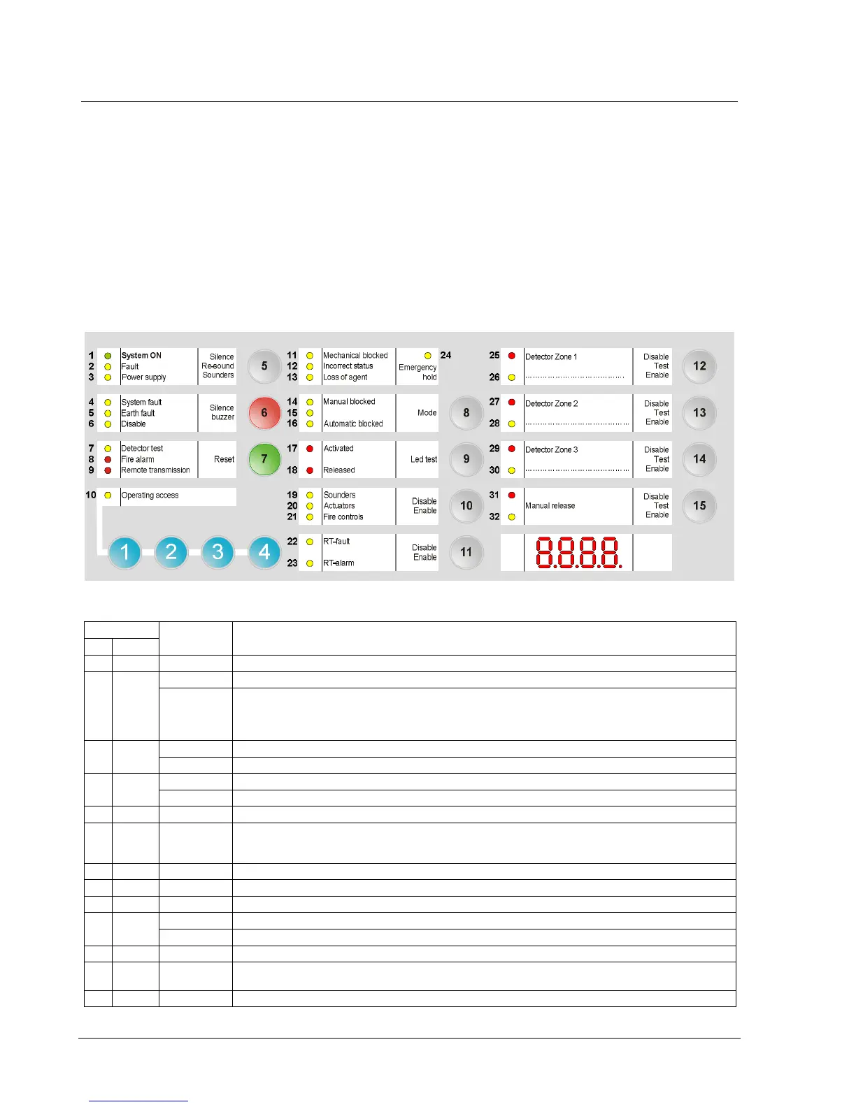
4.6 User interface
All display and control elements, except 4-digit display for XC1001-A version, are
accessible to the user:
- Led 1 to 32 indicators for operating condition,
- Keys 1 to 15 allowing :
è operating access
è operation (reset, off, test, etc)
è system test
è user functions programming
- 4-digit display showing:
è programming steps and options
è pre-discharged warning time count down
è other information’s (calibration states, alarm counter, etc)
Fig. 6 XC100x-A, user interface
Indicators
State Description
N° Color
1 Green Fixed The control panel is in operation
2 Yellow Fixed The control panel is not able to function any more
Fast Fault on at least one component in the system (see paragraph 14.2 for the detail)
Or,
Non-monitorred Control Input 3 is in active state, assuming it is programmed as “External device fault”
(Step50 – Option7)
3 Yellow Slow Mains fault
Fast Batteries fault
4 Yellow Fixed Microprocessor fault
Slow Jumper buzzer (X3 - XCM1002 board) not connected (remainder)
5 Yellow Fast At least one component connected to the control panel is grounded
6 Yellow Fixed – At least one component in the system is disabled
– Calibration in progress or error
– Programming in progress
7 Yellow Slow At least one detection zone and/or extinguishing manual control is being tested
8 Red Fixed At least one detection zone is in alarm
9 Red Fixed Remote transmission activated (according to programming)
10 Yellow Fixed Level 2 operating access granted
Slow System test activated
11 Yellow Fixed Mechanical blocking device is in the blocked position
12 Yellow Fast – Mechanical blocking device is in a wrong position
– Selector valve is in a wrong position (used for multi-sector applications)
13 Yellow Fast Loss of agent
 Loading...


