Connections
39
Building Technologies A6V10257473_e_en_--
Fire Safety 2015-03-04
Option 01 at step 02 must be imperatively selected in case of pyrotechnic actuator and not be
selected in case of electromagnetic actuator.
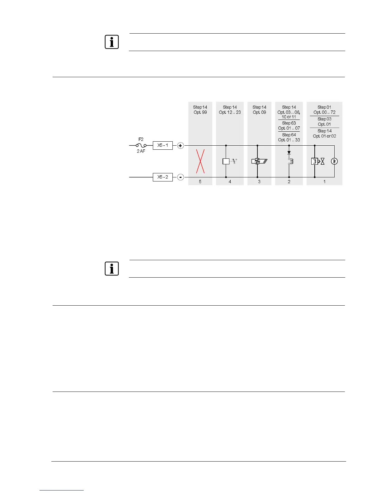
7.6.5 Monitored control output 5
This output can be used for several purposes. Operation is defined at programming
steps 01, 03, 14, 63 and 64 (see paragraphs 12.3, 12.6 and 12.6).
Fig. 26 XC100x-A, monitored control output 5 connection
1 Actuators (electromagnetic or pyrotechnic)
2 Fire control(s): signal triggering to equipment outside the system according to
EN12094-1 option with requirements 4.26
3 Extract fan
4 Others (example: relay)
5 Output not used (no EOL required)
If this output is used to connect actuators, characteristics of the monitored output 4 (line length,
programming options, etc.) apply.
7.7 Programmable outputs
An output, among those described in this chapter, must obligatorily be
programmed to transmit the following information’s:
- « Emission » (in all cases)
- « Mechanical blocking »
(1)
- « Emergency hold/abort »
(1)
- « Automatic blocked » (in all cases)
(1)
When these options with requirements are used.
7.7.1 Driver outputs
Eight programmable drivers outputs (non-monitored), are available on X12 terminal
block. Operation is defined at programming steps 20 to 27 (see paragraph 12.8).
Technical data
Open collector type 24 Vcc – 40mA max.
 Loading...


