Multi-sector installation
47
Building Technologies A6V10257473_e_en_--
Fire Safety 2015-03-04
affected.
All manometer or weighing devices must be connected to the XCA1031 loss of
agent line (control cylinder and main cylinder bank). All contacts must be
connected in series (special cables connection are available: TOR-UNIT, TOR-
MULTI, TOR-END). Normally closed contact must be used (i.e pressure or quantity
of gas is correct when the contact is closed). If one contact opens, the XCA1031
sends a fault message via the multi-sector bus and all XC10’s “Loss of agent” leds
are turned on. If the line is in fault condition, the XCA1031 sends a fault message
via the multi-sector bus and all XC10’s “Fault” leds are turned on.
The activation line informs the XCA1031 module that one of the XC10s connected
in the system is activated. If the activation line is in fault condition (short-circuit or
disconnection), the XCA1031 sends a fault message via the multi-sector bus and
all XC10’s “Actuator fault” leds are turned on.
Once a sector is activated, the new condition is transferred to the XCA1030
module, which closes the activation line resistor switch. The “Alarm” condition of
the activation line informs the XCA1031 module that one of the extinguishing
sectors is activated. Then, the XCA1031 activates the redundant actuator line,
which causes the release of the control cylinder. The inter-blocking information is
automatically sent from the XCA1031 to all connected XC10s via the Multi-sector
bus, and all XC10’s which are in standby condition, are blocked (only the actuator
control line is blocked).
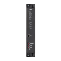
Fig. 32 XCA1031 multi-sector common module
Mark Pin Function
X1 1 (+) / 2 (–) 24 V power supply input N° 1
3 (+) / 4 (–) 24 V power supply input N° 2
X2 1 (–) / 2 (+) Loss of agent monitored input
3 (–) / 4 (+) Activation line
5 (–) / 7 (+)
Multi-sector bus (RS485)
6 (–) / 8 (+)
X3 — RS485 bus configuration jumper (see paragraph 8.3)
X4 1 (+) / 2 (–) Actuator line 1 (indicated polarities are control polarities)
3 (+) / 4 (–) Actuator line 2 (indicated polarities are control polarities)
X5 — Ground connection
H1 / H2 — 24V power supply input indications (H1: input 1, H2: input 2)
F1 / F2 — 1 AF fuse protection for actuator lines 1 (F1) and 2 (F2)

 Loading...


