Installation and Startup
Rev. 7 August 2021 27 41110485
I/O Pins
You can use the I/O pins as:
• Digital inputs
(See Table 2-2 on page 27 and Figure 2-19 on page 27.)
• High side pull-ups/dry contact switch inputs
(See Figure 2-20 on page 28.)
• Analog inputs
(See Table 2-3 on page 29 and Figure 2-22 on page 29.)
• Low side current sinks
(See Figure 2-23 on page 29.)
• Digital outputs/open drains
(See Table 2-4 on page 30 and Figure 2-24 on page 30.)
Note: The I/O pin functionality is programmable in Legato applications.
Digital Input
Digital input is available on I/O 1, I/O 2, and I/O 3 on the power connector.
Note: To use I/O 3 as a digital Input, GPIO56 (that drives I/O 3 when used as a digital output) must
be low.
You can connect any of these pins to a digital input to detect the state of a digital sensor
or pulse counter.
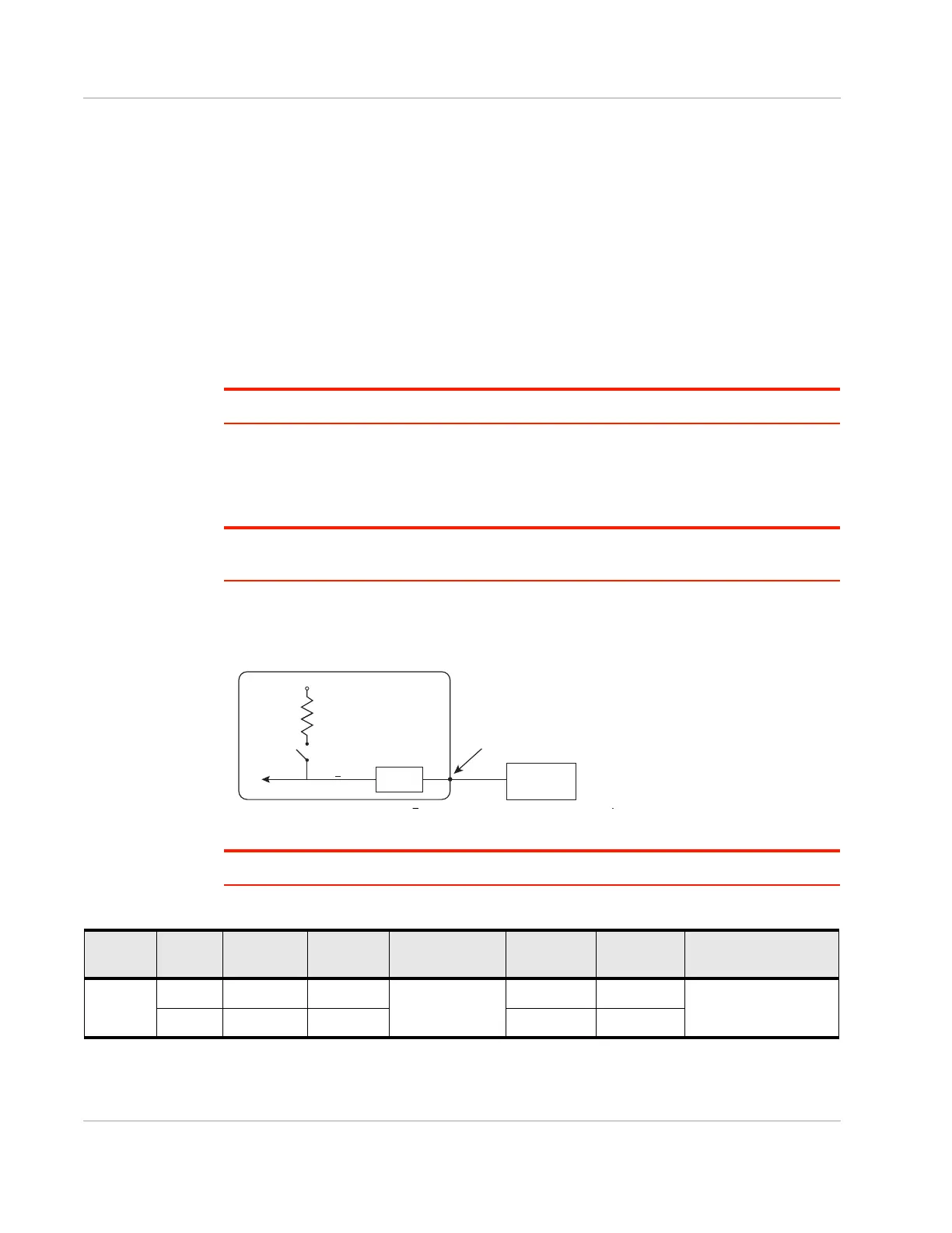
Figure 2-19: Digital Input
Note: When using a digital input, the pull-up should be Off.
Gateway
Off
V
in
or 3.3 V*
Internal Pull-up
10 k
Resistor
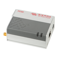
FX30
Digital input
Internal pull-up
NſUHVLVWRU
Off
V
High ! 3.0 V
I/O 1, I/O 2, I/O 3
RQWKHSRZHUFRQQHFWRU
3URWHFWLRQ
FLUFXLWU\
Vin RU V
Table 2-2: Digital Input Voltage Ranges
Pull-up State Normal
Min.
Normal
Max.
Normal Input
Impedance
Extended
Min.
Extended
Max.
Leakage Current in
Extended Range
Off Low -33.0 V +1.0 V
>150 kOhm
-36.0 V —
1 mA max.
High +3.0 V +33.0 V — +36.0 V
 Loading...