Sierra Wireless FX30S User Guide
Rev. 7 August 2021 24 41110485
Wiring Diagrams
In the following diagrams, FX30 refers to either FX30 and FX30S.
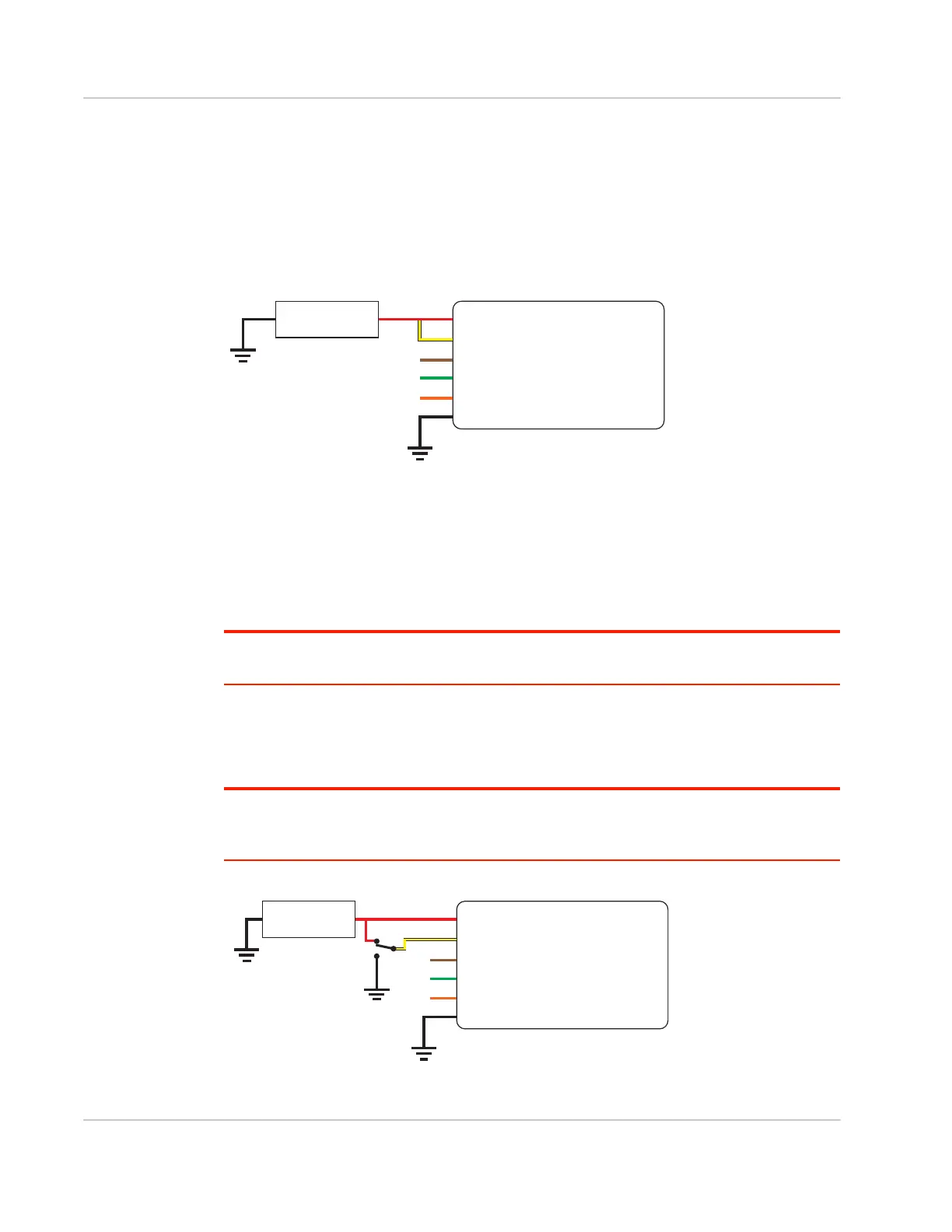
Always On Installation
For an Always On application, connect the wires as shown in Figure 2-15.
Figure 2-15: Always on installation
• Pin 1 (Power)—Use the red wire in the DC cable to connect Pin 1 to the power
source.
• Pin 2 (Ground)—Use the black wire in the DC cable to connect Pin 2 to ground. See
also Step 2—Mount and Ground the FX30S Chassis on page 13.
• Pin 3 (On/Off)—Connected to power
• Optional—I/O 1, I/O 2, and I/O 3
Note: See Table D-1, FX30S Hardware Feature to Linux Interface Mapping, on page 78 for the
radio module GPIO and Linux interface mapping of pin 3, I/O 1, I/O 2, and I/O 3.
On/Off Installation
For an On/Off application, connect the wires as shown in Figure 2-16 or Figure 2-17.
Note: When using GPIO24 to monitor the ignition state, connect a SPDT switch as shown in
Figure 2-16 or sensor with pulldown as shown in Figure 2-17. Otherwise, a switch or sensor is not
required.
Figure 2-16: On/Off Installation with switch
Gateway
Power
On/Off
Ground
DC power source
1
3
2
I/O1
I/O2
I/O3
FX30
DC power source
2 Ground
I/O 3
I/O 2
I/O 1
1 Power
3 On/Off
FX30
DC power source
2 Ground
I/O 3
I/O 2
I/O 1
1 Power
3 On/Off
SPDT switch