Installation and Startup
Rev. 7 August 2021 25 41110485
• Pin 1 (Power)—Use the red wire in the DC cable to connect Pin 1 to the power
source.
• Pin 2 (Ground)—Use the black wire in the DC cable to connect Pin 2 to ground. See
also Step 2—Mount and Ground the FX30S Chassis on page 13.
• Pin 3 (On/Off)—Connect Pin 3 to the pole of a SPDT switch. Connect the NC throw to
power, and the NO throw to ground.
Pin 3 must be connected.
• Optional—I/O 1, I/O 2, and I/O 3
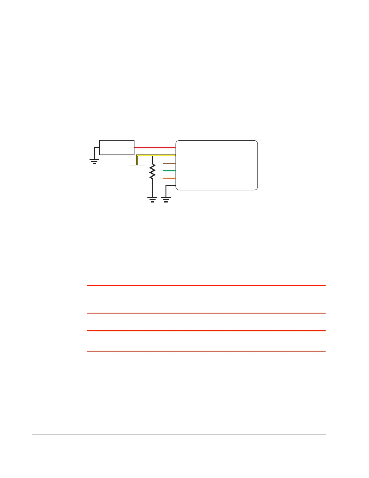
An On/Off installation may also use a sensor as a switch to turn the FX30S on or off, as
shown in Figure 2-17.
Figure 2-17: On/Off Installation (with sensor)
• Pin 1 (Power)—Use the red wire in the DC cable to connect Pin 1 to the power
source and the collector pin of the transistor.
• Pin 2 (Ground)—Use the black wire in the DC cable to connect Pin 2 to ground. See
also Step 2—Mount and Ground the FX30S Chassis on page 13.
• Pin 3 (On/Off)—The On/Off pin of the FX30S can be enabled or disabled using a
sensor. Additional circuitry may be required, such as using a transistor to control the
On/Off pin based on the output of the sensor.
Pin 3 must be connected.
Note: When using GPIO24 to monitor the ignition state, if GPIO24 does not read the on/off state
correctly and always returns 0, then a 1K external pull-down resistor must be added, as shown in
Figure 2-17.
• Optional—I/O 1, I/O 2, and I/O 3
Note: See Table D-1, FX30S Hardware Feature to Linux Interface Mapping, on page 78 for the
radio module GPIO and Linux interface mapping of pin 3, I/O 1, I/O 2, and I/O 3.
Gateway
Power
On/Off
Ground
DC power source
1
3
2
I/O1
I/O2
I/O3
Sensor
NPN
FX30
DC power source
2 Ground
I/O 3
I/O 2
I/O 1
1 Power
3 On/Off
Sensor
 Loading...