Sierra Wireless FX30S User Guide
Rev. 7 August 2021 26 41110485
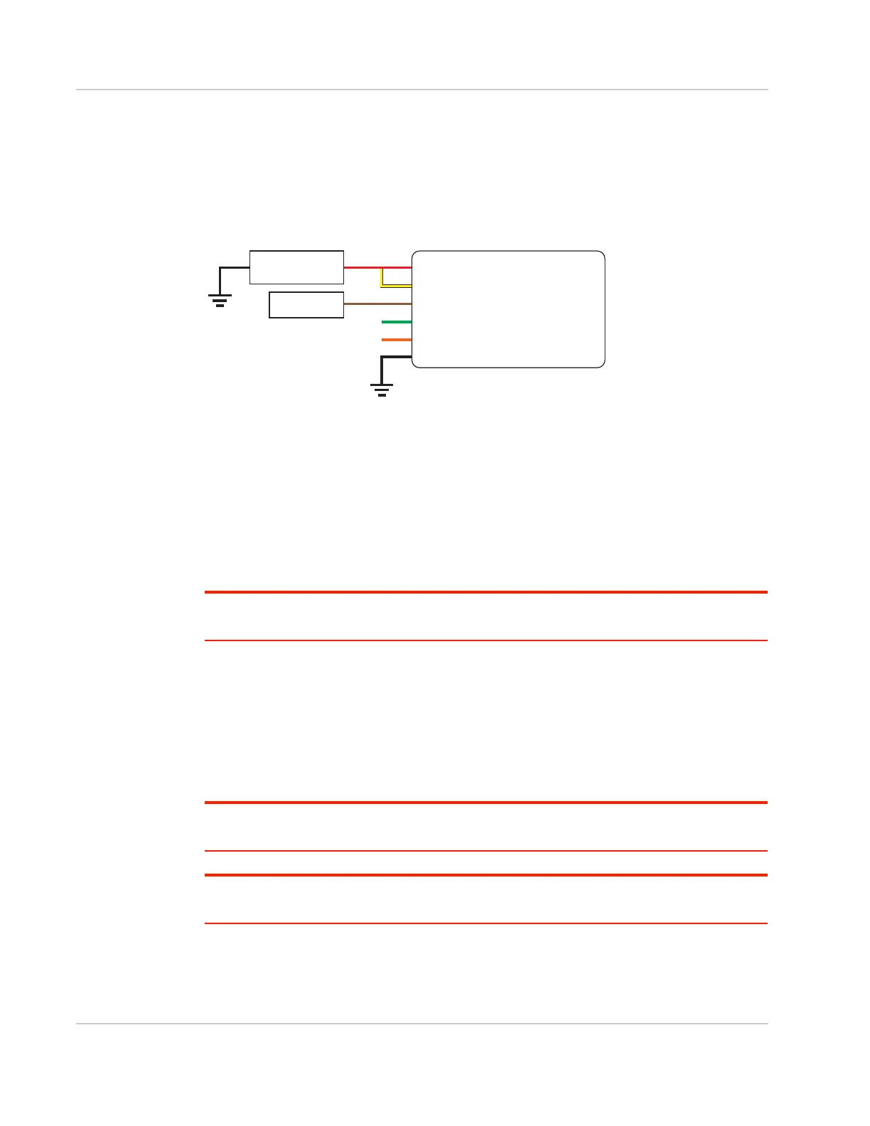
Installation with I/O Input Triggered by Standby Mode
If you have an installation where you want to use the I/O to monitor an external device
such as a motion detector or gate sensor, refer to Figure 2-18. If desired, you can use
Legato to program the I/O line to wake the gateway from ultra low power mode for a
specific length of time.
Figure 2-18: Fixed Installation with I/O
• Pin 1 (Power) —Use the red wire in the DC cable to connect Pin 1 to the power
source.
• Pin 2 (Ground)—Use the black wire in the DC cable to connect Pin 2 to ground. See
also Step 2—Mount and Ground the FX30S Chassis on page 13.
• Pin 3 (On/Off)—Connected to power
Pin 3 must be connected.
• I/O 1—configured for digital input
• Optional—I/O 2 and I/O 3
Note: See Table D-1, FX30S Hardware Feature to Linux Interface Mapping, on page 78 for the
GPIO and Linux interface mapping of pin 3, I/O 1, I/O 2, and I/O 3.
I/O Configuration
The FX30S power connector has three pins you can use for I/O configuration:
• I/O 1—Digital input only; allows wakeup from ultra low power mode
• I/O 2—Digital and analog input
• I/O 3—Digital input and digital output
Note: See Table D-1, FX30S Hardware Feature to Linux Interface Mapping, on page 78 for the
GPIO and Linux interface mapping of the I/O pins.
Note: The IoT Expansion Card has four GPIO pins that you can program using Legato. For details,
refer to the IoT Expansion Card Design Specification.
DC power source
Gateway
Power
On/Off
Ground
Motion sensor
1
3
2
I/O1
I/O2
I/O3
FX30
DC power source
2 Ground
I/O 3
I/O 2
I/O 1
1 Power
3 On/Off
Motion sensor