EasyManua.ls Logo

Siko AG05 - Flow Chart: Operating Mode: Positioning Mode

Siko AG05
64 pages
Print Icon
To Next Page IconTo Next Page
To Previous Page IconTo Previous Page
Loading...
Service Protocol
AG05
Date: 15.06.2016 Art. No. 85677 Mod. status 139/16 Page 46 of 64
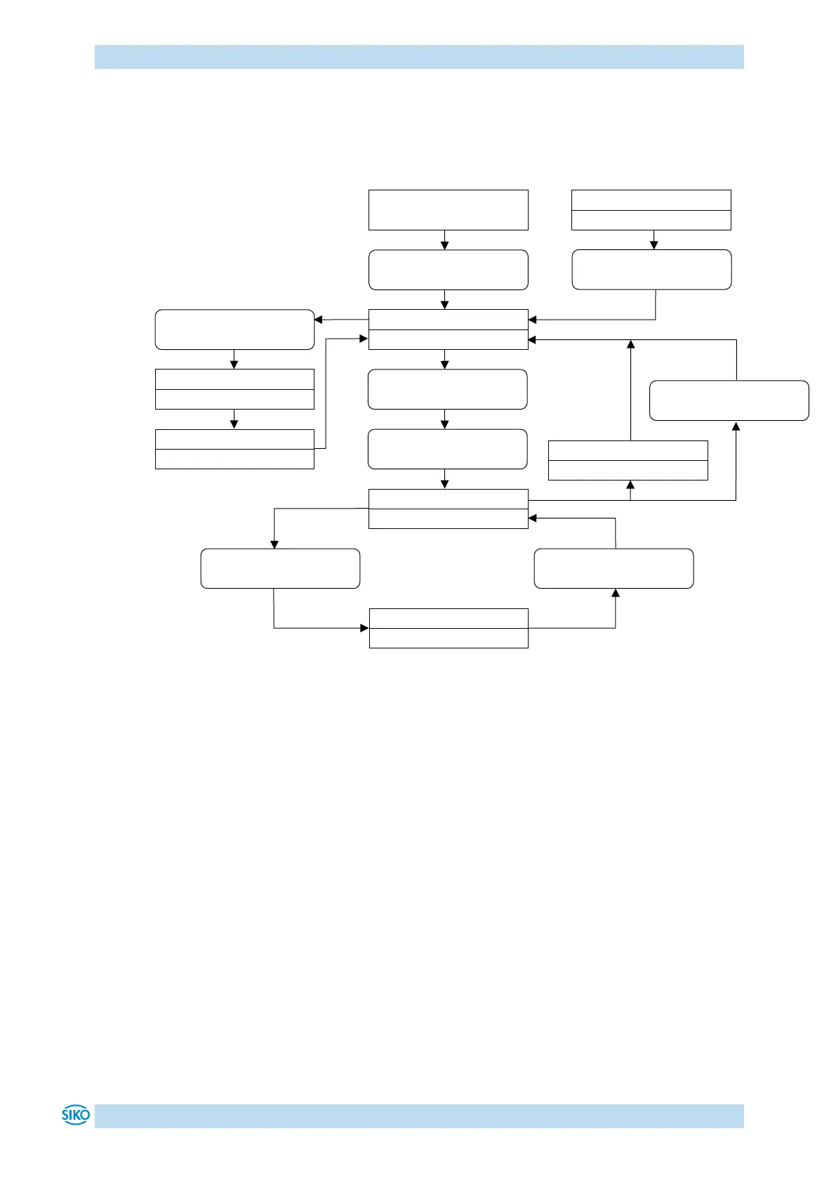
9.5 Flow chart: Operating mode: Positioning mode
The flow chart below shows the control of positioning in the positioning mode via service
protocol (see chapter 9: Service Protocol).
Fig. 8: Flow chart positioning mode service protocol
Acknowledge error
command 'S11103'
Start
Supply voltage ON
Read status word
command 'R'
Operation enabled
SW = 000x 0000 x000 x000
Send set point
command 'F0'
Start positioning
command 'M'
Travelling order active
SW = x1xx 10x0 0001 0000
Continue positioning
command 'M'
Error
Status word bit 8 = '1'
Intermediate stop active
SW = x10x 00x0 0000 0000
Intermediate stop
command 'N' oder 'O'
Start inching 1/2
command 'Y' / ',' / '.'
Inching order active
SW = x0xx 1000 0001 0000
Inching order finished
SW = 000x 0000 0000 x000
SW = System status word
x = Bit can be '0' or '1'
Target position reached
SW = 000x 0000 0000 1000
Finish travelling order
command 'I'

Table of Contents