EasyManua.ls Logo

Siko AG05 - Flow Chart: Positioning Mode

Siko AG05
64 pages
Print Icon
To Next Page IconTo Next Page
To Previous Page IconTo Previous Page
Loading...
Communication via SIKONETZ5
AG05
Date: 15.06.2016 Art. No. 85677 Mod. status 139/16 Page 53 of 64
Bit
Description
Bit 11
Battery warning
0 = no warning, battery loading state is OK
1 = Battery warning
Battery voltage is below 2.6 V.
Battery change is required.
Bit 12
Current limiting
0 = current limiting inactive
1 = current limiting active
Motor current exceeds the value set under parameter 0x2C.
Table 20: Status word positioning mode SIKONETZ5
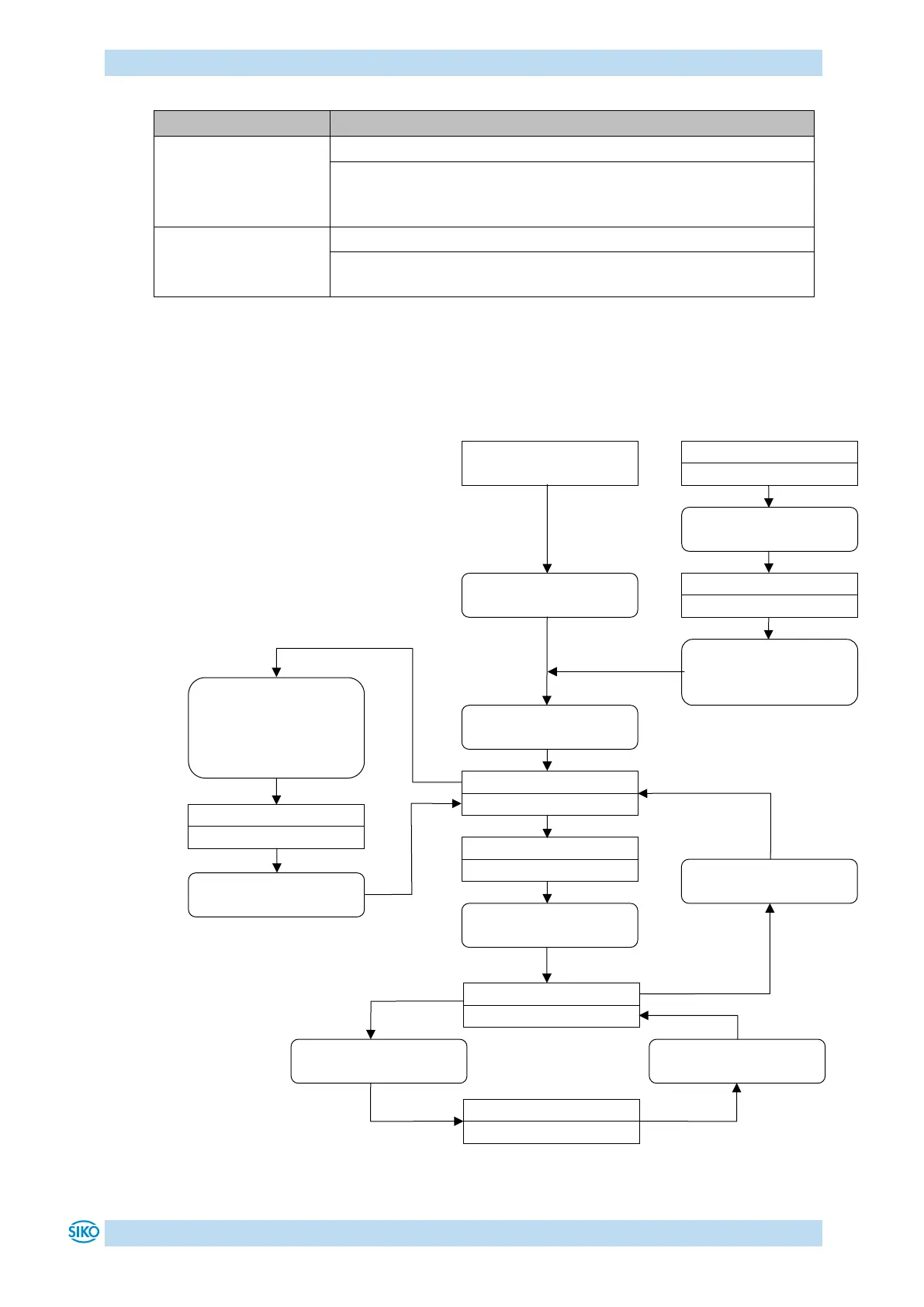
10.8.3 Flow chart: Positioning mode
Fig. 10: Flow chart positioning mode SIKONETZ5
Activate travel job
CW = 0000 0000 0001 0111
Operation enabled
SW = 0000 x001 00x0 xxx1
enable operation
CW = 0000 0000 0000 0111
Ready to travel
SW = 0000 x001 00x0 0011
Travel order active
SW = 000x x101 01x1 0001
Intermediate stop
CW.3 = 1
Intermediate stop active
SW = 0000 x101 01x0 0011
Continue positioning
CW.3 = 0
Inching 1/2 ON
CW = 0000 0000 0100 0111 or
CW = 0000 0000 1000 0111 or
CW = 0000 0001 0000 0111
Inching 1/2 active
SW = 000x x001 00x1 0001
Inching OFF
CW = 0000 0000 0000 0111
Travel order finished
Error
SW.7 = 1
Acknowledge error
CW.5 = 1
Switch lock
SW.9 = 1
OFF1 CW.0 = 1/0 or
OFF2 CW.1 = 1/0 or
OFF3 CW.2 = 1/0
Start
Supply voltage ON
CW = 0000 0000 0000 0000
CW = Control word SIKONETZ5
SW = Status word SIKONETZ5
x = Bit can be '0' or '1'

Table of Contents