Service Protocol
AG05
Date: 15.06.2016 Art. No. 85677 Mod. status 139/16 Page 33 of 64
9 Service Protocol
9.1 General
The service protocol enables drive configuration and control via ASCII commands. No
additional devices must be connected to the RS485 interface since this protocol is not bus-
compatible.
This user manual is valid with Motor controller firmware version V1.11!
The PC sends a letter and additional parameters if required (ASCII).
Subsequently, the AG05 sends a reply with a concluding <CR>.
Parameters: 19200 / 57600 / 115200 baud, no parity, 8 data bits, 1 stop bit, no handshake
9.2 System Status Word
The system status word consists of 2 bytes and reflects the state of the actuator (see chapter
8: Parameter description Parameter no. 73).
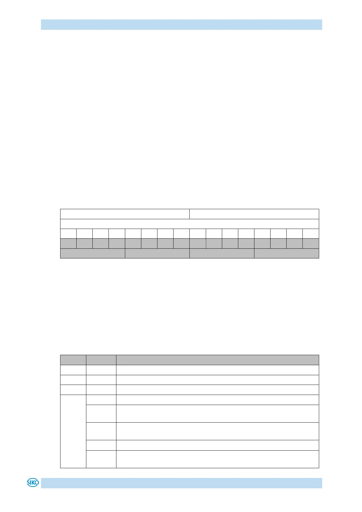
Table 14: Structure of system status word
Example (grey background):
binary: 0010 1001 0100 1000
hex: 2 9 4 8
9.2.1 Meaning of the bits
The table below informs about the meaning of the individual bits of the status word:
Operating mode: Positioning mode In Position
Actual position is within the positioning window of the programmed set
point.
Actual position is beyond the positioning window of the programmed set
point.
Operating mode: Speed mode: In Position
Actual rotational speed is within the specified tolerance window of the
target speed.