Sirona Dental Systems GmbH 12 Electrical Connection
59 58 470 D 3370
D 3370.031.01.10.02
17
båÖäáëÜ
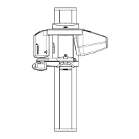
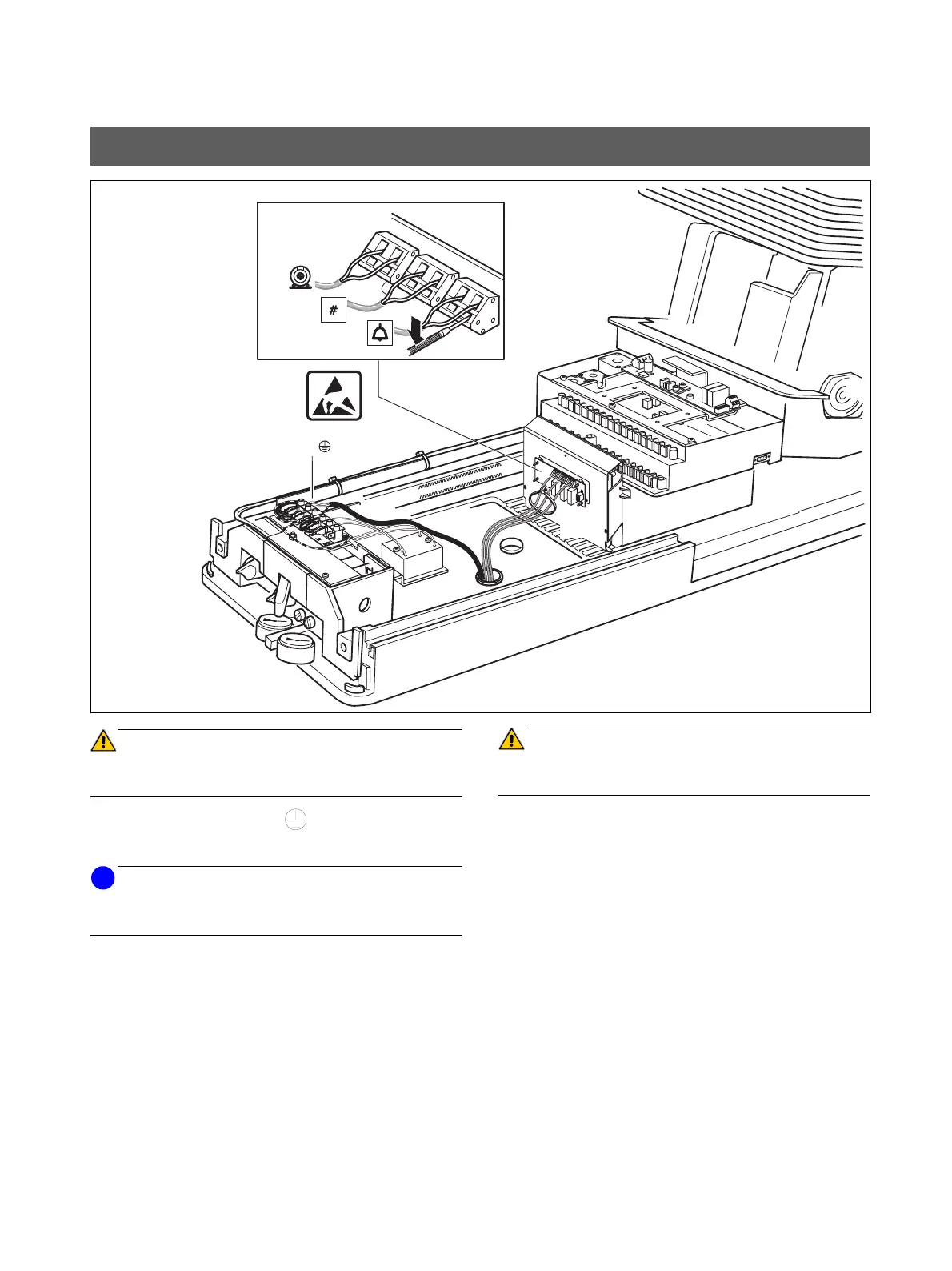
ATTENTION
Switch OFF power from the main switch for the electrical in-
stallation.
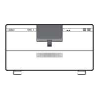
1. Connect power line: N, L,
2. Connect control leads of suction pump to X4.47 and 49.
NOTE
i
Connecting technique for X2, X3, X4:
First press with a screwdriver, and then plug in.
3. Connect call leads to X2.1 and 2. Only the push-button
function is possible.
4. X3.3 and 4 are terminal points for key # (for example,
composite function of the ceiling model SIROLUX FAN-
TASTIC, when present).
With the SIROLUX FANTASTIC ceiling model, two ca-
bles have to be laid from the ceiling to the installation
tube in the connection area of the chair.
Note setting as switch or push-button (momentary).
(See Operating Instructions, chapter ”Basic Work-
station Settings, Mode Key”).
ATTENTION
The control voltages connected to X2, X3 and X4 may
amount to max. 230V, 6A.
5. Fasten the control cables from X2, X3 and X4 together
with a cable tie.
• Switch ON power from the main switch for the electrical
installation.
12 Electrical Connection
1
2
3
X3
X2
X4
4
49
47
L
N
1.
2.
3.
4.
5.