28 Compare and adjust operating air pressures Sirona Dental Systems GmbH
59 58 470 D 3370
38 D 3370.031.01.10.02
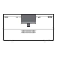
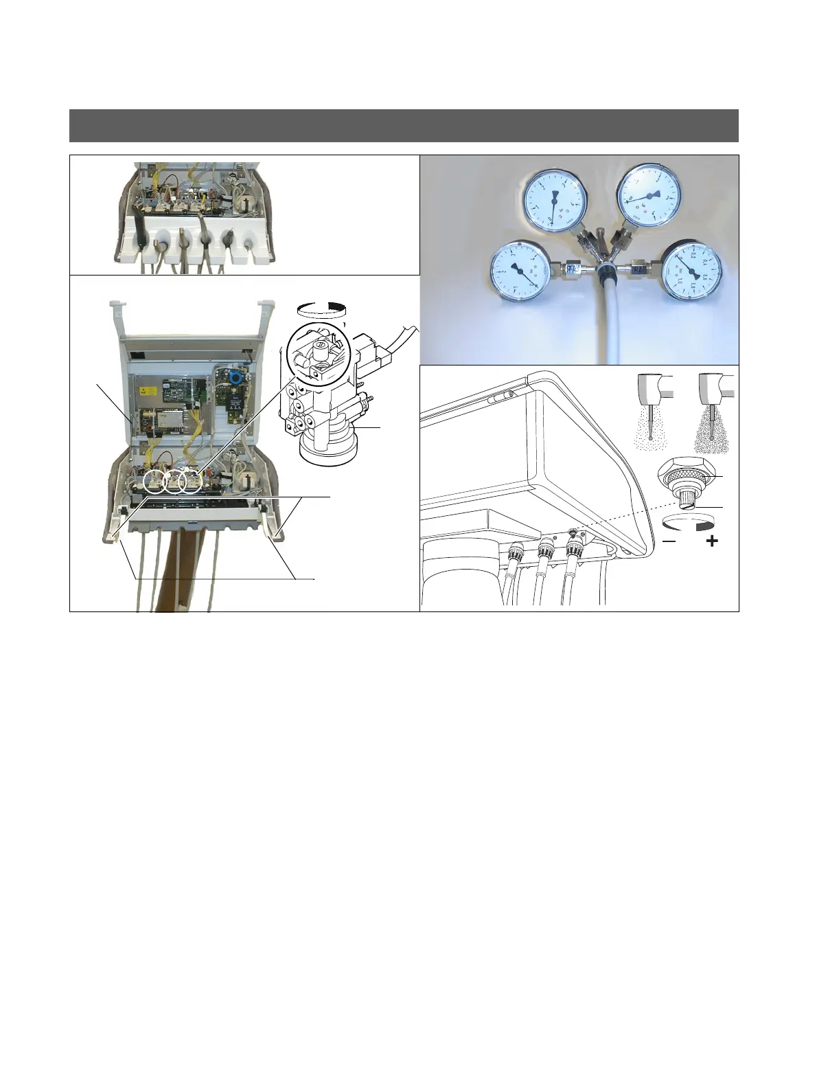
Setting the Air Pressures
Propellant air
The setting is performed separately for each turbine on the
chip BS concerned.
• Take the instruments from their holders.
• Press down two catches A and remove the instrument
tray.
• Loosen screws B.
• Lift back the unit cover C, and secure with the upright
retaining device D.
• Set down the instrument tray temporarily and return the
instruments to their holders (photelectric light barrier
detection must function).
• Remove the turbine and screw 4-on-1 probe V between
the turbine and hose.
• Start the turbine with the foot switch.
• Set the pressure of the propellant air at RD5 with a
screwdriver.
Do not undo the screw further than to the level of
the plastic collar.
• Repeat setting for other holders.
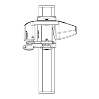
• Close the unit head:
– Take out the instruments and remove the instru-
ment tray.
– Fold down the unit head and install screws B.
When installing the unit head, make sure that is
centered with respect to the chassis so that
gaps of identical size are created when the
instrument tray is mounted.
– Put the instrument tray in place and lay the instru-
ments on it.
Spray air
• Connect the 4-on-1 probe.
• Undo union nut M.
• Using a screwdriver, set spray air pressure SL as re-
quired by the customer by turning screw S.
• Tighten union nut M
• Check the settings and readjust if necessary.
• Remove the 4-on-1 probe.
BS
RD5
-+
A
B
C
D
V
S
M
TL
SL