Section 04 ENGINE
Subsection 03 (494, 583 AND 670 ENGINE TYPES)
04-03-7
NOTE:
Neither exhaust manifold nor cylinder
aligning tools (flat bars) must be installed on ex-
haust flanges to perform this procedure.
1. Place a 0.43 mm (.017 in) feeler gauge be-
tween cylinders and slide it back and forth to
have the good spacing along cylinders.
A. 0.43 mm (.017 in) feeler gauge
2. Apply Loctite 242 to screw threads. Properly
torque cylinders screws.
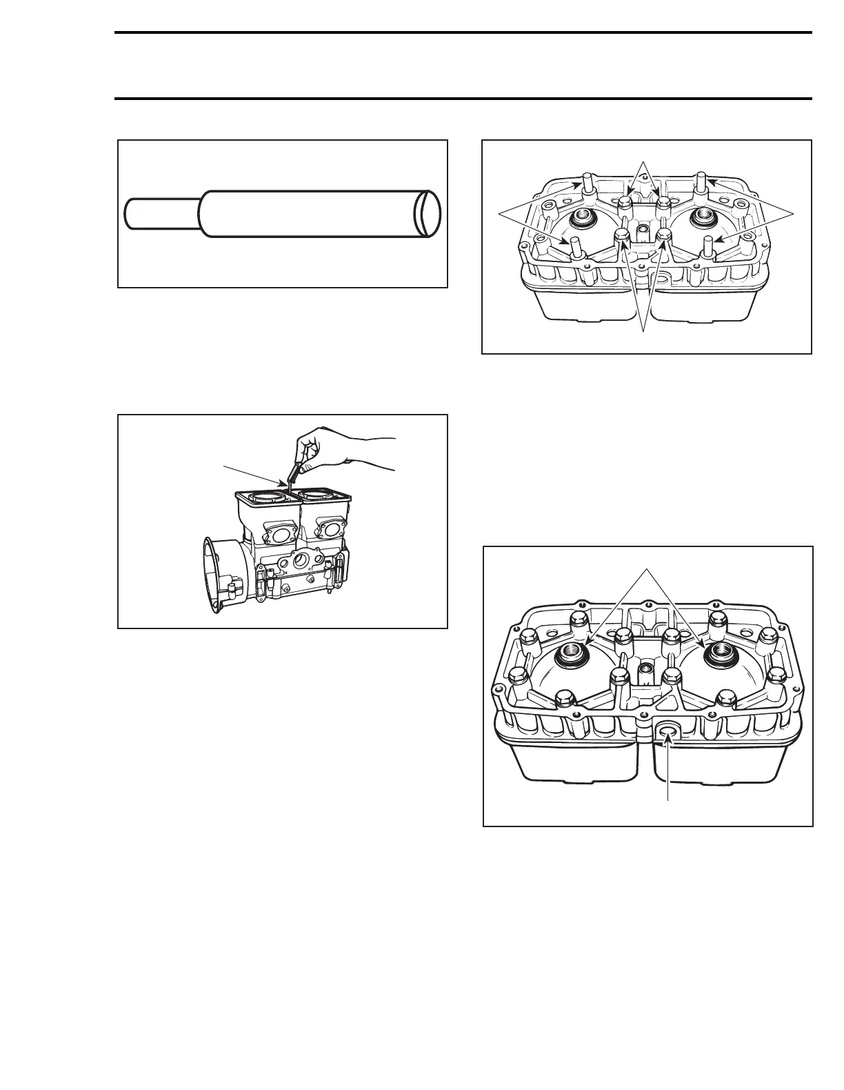
3. Lay down cylinder head and insert aligning pins
in holes as shown.
NOTE:
If pins can not be inserted in cylinder head
holes, enlarge them with a 8.75 mm (11/32 in) drill
bit.
4. Install 4 screws in center holes. Torque to 10
N•m (89 lbf•
in
).
1. Pins
2. Screws
5. Remove pins and install remaining screws.
6. Tighten all screws in the above-recommended
sequence and torque as specified.
Position O-rings over cylinders then install cylinder
head with its temperature sensor hole on rotary
valve side. Install and torque screws to 29 N•m (21
lbf•ft) as per following illustrated sequence. Make
sure to install O-rings around spark plug holes.
TYPICAL
1. O-rings
2. Temperature sensor hole
A. Torque to 29 N•m (21 lbf•ft)
A00A1DA
A00A1FA
A
A00A1EA
2
2
1
1
A25C0CA
1
2
A
 Loading...

