Section 11 WIRING DIAGRAMS
Subsection 01 (WIRING DIAGRAMS)
11-01-1
WIRING DIAGRAMS 0
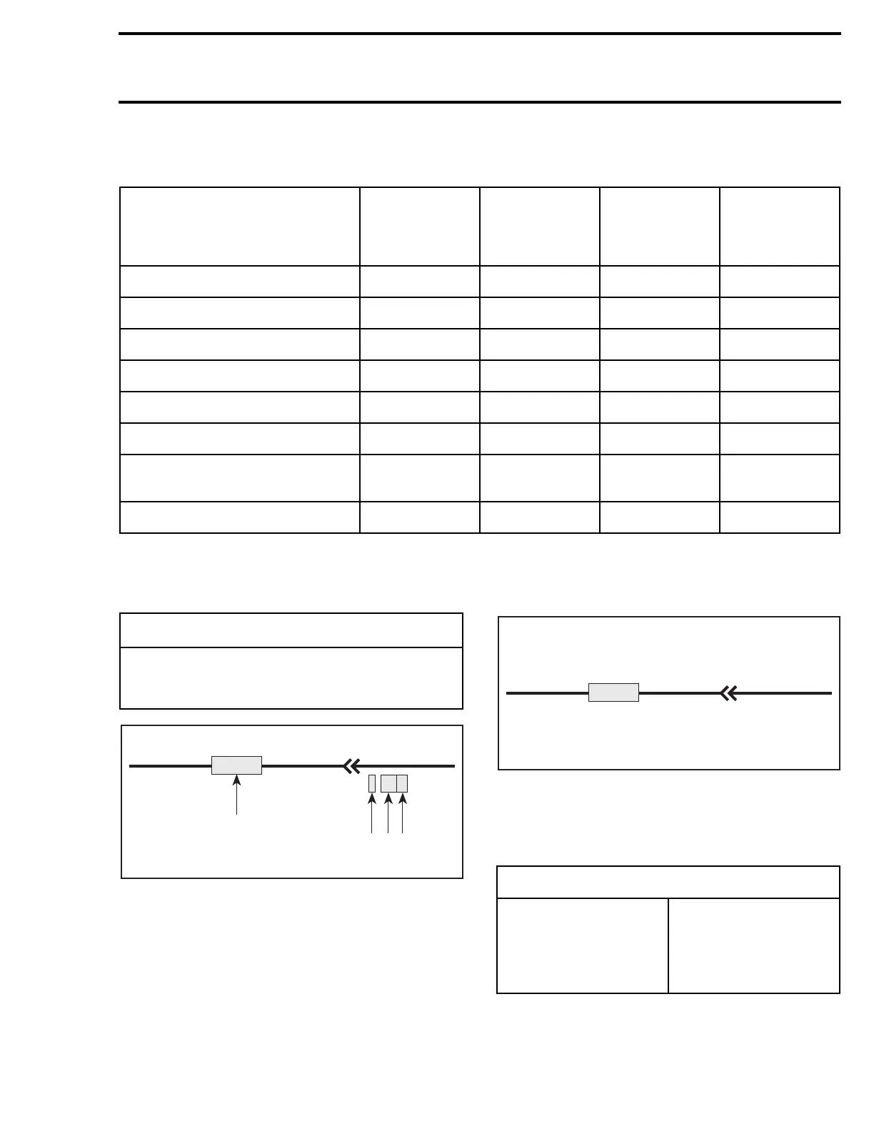
WIRING DIAGRAM LEGEND
1. Wire colors
2. Housing area
3. Housing number per area
4. Wire connector location in housing
WIRE COLORS AND CIRCUIT
The first color of a wire is the main color, second
color is the stripe.
Example: YL/BK is a YELLOW wire with a BLACK
stripe.
MODEL
WIRING
DIAGRAM
PAGE
HEADLIGHT
(watt)
TAILLIGHT
(watt)
ELECTRICAL
SYSTEM
OUTPUT
(watt)
Skandic WT/SWT Annex 1 60/55 hal. 8/27 240
Skandic WT LC Annex 2 60/55 hal. 8/27 220
MX Z 440 Annex 3 60/55 hal. 8/27 240
MX Z 500/583/670 Annex 4 60/55 hal. 8/27 220
Formula Z 583/670 Annex 5 60/55 hal. 8/27 220
Formula 500 DL/583 DL Annex 6 60/55 hal. 8/27 220
Formula 500
Summit 500/583/670
Annex 7 60/55 hal. 8/27 220
Grand Touring 500/583 Annex 8 60/55 hal. 8/27 220
hal. = halogen
;
WARNING
Ensure all terminals are properly crimped on
the wires and all connector housings are
properly fastened.
A00I04A
XX/XX
1-02D
1
2 3 4
COLOR CODE
BK – BLACK
WH – WHITE
RD – RED
BL – BLUE
YL – YELLOW
GN – GREEN
GY – GREY
VI – VIOLET
OR – ORANGE
BR – BROWN
A00I04B
XX/XX
1-02D
 Loading...

