Section 04 ENGINE
Subsection 11 (CARBURETOR AND FUEL PUMP)
04-11-5
VIEW FROM AIR INTAKE OPENING
NOTE:
For fine tuning refer to TECHNICAL DATA
10 and to SPARK PLUG 06-03.
NOTE:
For high altitude regions, the
High Altitude
and Sea Level Technical Data Booklet
(P/N 484
0686 00 and 484 0545 00 for binder) gives infor-
mation about calibration according to altitude and
temperature.
INSTALLATION
To install carburetor on engine, inverse removal
procedure.
However, pay attention to the following:
– Inspect throttle cable and housing prior to in-
stallation.
On applicable models, make sure to align tab of
carburetor and air intake silencer (if applicable)
with notch of adaptor(s). On applicable models, in-
stall adaptor with up mark facing up.
Install clamps in a way that their tightening bolts
are staggered — not aligned.
Hook throttle cable into the needle retainer plate.
NOTE:
Do not obstruct hole in throttle slide when
installing needle retaining plate. This is important
to allow air escaping through and thus allowing a
quick response.
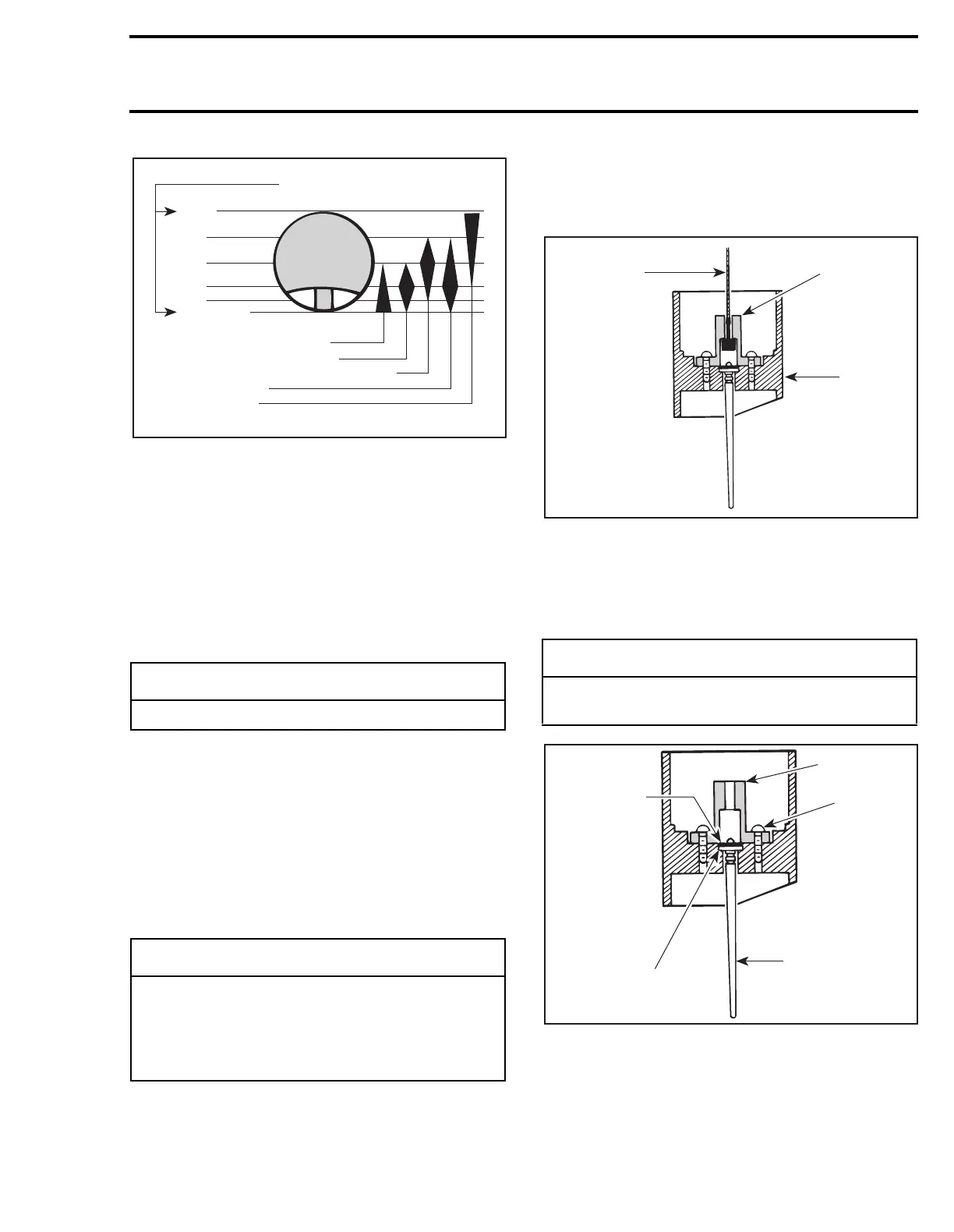
CENTER POST TYPE
1. Throttle cable
2. Needle retaining plate
3. Throttle slide
Make sure the nylon packing
no. 4
is installed on
all applicable throttle slides.
CENTER POST TYPE
1. E-clip
2. Needle retaining plate
3. Screw
4. Needle
5. Nylon packing
-
CAUTION
Never allow throttle slide(s) to snap shut.
-
CAUTION
The rubber flange must be checked for
cracks and/or damage. At assembly, the
flange must be perfectly matched with the
air intake manifold or severe engine damage
will occur.
Throttle slide openings
Pilot jet and air screw13,6,
Throttle slide cut-away5,
Needle taper and needle position3,
Needle jet14,
Main jet8,
A00C04A
Wide
open
Close
3/4
1/2
1/4
1/8
-
CAUTION
Serious engine damage can occur if this no-
tice is disregarded.
A00C1TA
1
2
3
2
3
4
5
1
A00C3MA
 Loading...

