Section 06 ELECTRICAL
Subsection 05 (ELECTRIC STARTER)
06-05-2
REMOVAL
– Disconnect BLACK ground cable from battery.
– Disconnect RED positive cable from battery.
– Disconnect RED cable and RED/GREEN wire
from starter solenoid switch.
– Remove starter from engine.
DISASSEMBLY
Disconnect bare wire linking starter and solenoid.
Remove nuts
no. 16
then solenoid switch
no. 10
by lifting and pulling to disengage from drive lever
no. 15
.
Unscrew starter screws (long)
no. 1
then pull
yoke
no. 8
with end frame
no. 2
to separate from
drive housing
no. 17
.
Pull armature
no. 9
with drive lever
no. 15
.
Remove insulator
no. 4
then brush springs
no. 7
being careful not to lose them since they will be
projected out.
Pull brush holder
no. 5
from yoke
no. 8
.
Insert blade of a small screwdriver between stop
collars.
Twist screwdriver to separate stop collars
no. 12
thus giving access to circlip
no. 13
.
Remove outer collar, circlip then inner collar.
Remove overrunning clutch
no. 11
.
Check the wear on bushing
no. 18
by measuring
the amount of radial play between the armature
shaft and the bushing.
The radial play should not exceed 0.20 mm (.008 in).
If greater, replace the bushing. To replace, press
out the old one toward bushing cover and press in
a new one with a bushing pusher. The correct size
of the bushing pusher to use is given on next illus-
tration.
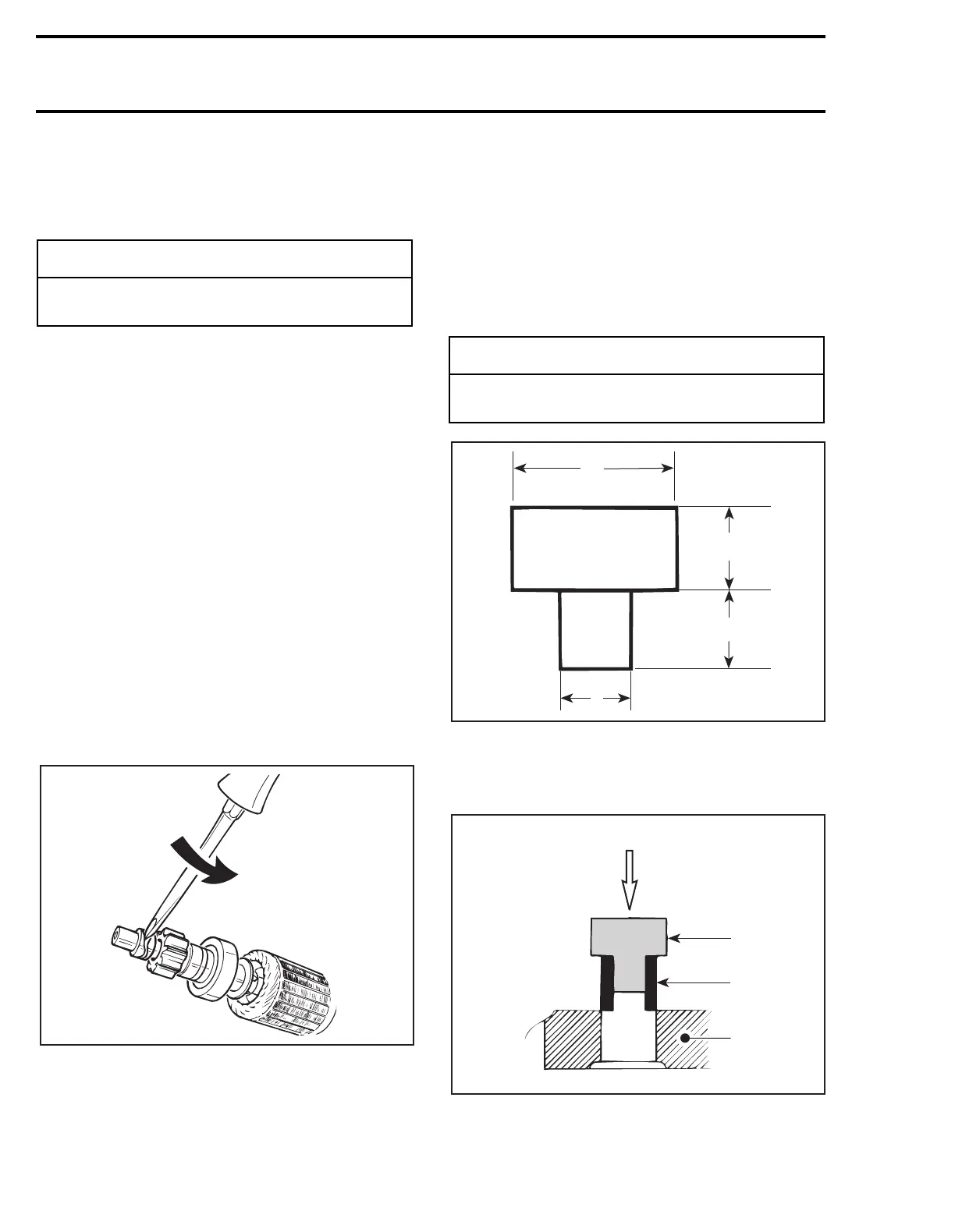
BUSHING PUSHER
A. 16 mm (5/8 in) dia.
B. 13 mm (1/2 in)
C. 11 mm (7/16 in)
D. 11.0 mm (.433 in)
1. Press-in
2. Bushing pusher
3. Bushing
4. Drive housing
◆
WARNING
Always disconnect ground cable first and
connect last.
A19E01A
-
CAUTION
Support drive housing adequately to pre-
vent damage when pressing bushing.
A19E0AA
B
C
D
A
D
A19E0BA
1
2
3
4
 Loading...

