Section 04 ENGINE
Subsection 04 (LEAK TEST AND ENGINE DIMENSION MEASUREMENT)
04-04-9
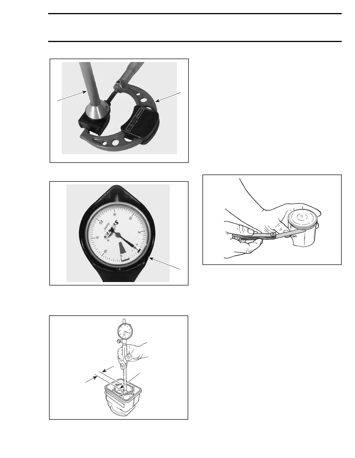
1. Use the micrometer to set the cylinder bore gauge
2. Dial bore gauge
1. Indicator set to 0
Position the dial bore gauge at 16 mm (5/8 in) be-
low cylinder top edge.
1. Measuring perpendicularly (90°) to piston pin axis
A. 16 mm (5/8 in)
Read the measurement on the cylinder bore
gauge. The result is the exact piston/cylinder wall
clearance. If clearance exceeds specified toler-
ance, replace cylinder or rebore. Refer to TECHNI-
CAL DATA 10.
NOTE:
Make sure the cylinder bore gauge indica-
tor is set exactly at the same position as with the
micrometer, otherwise the reading will be false.
RING/PISTON GROOVE
CLEARANCE
Using a feeler gauge check clearance between
rectangular ring and groove. Replace piston if
clearance exceeds specified tolerance. Refer to
TECHNICAL DATA 10-02.
RING END GAP
Position ring half-way between transfer ports and
intake port. On rotary valve engines, position ring
just below transfer ports.
NOTE:
In order to correctly position the ring in the
cylinder, use piston as a pusher.
Using a feeler gauge, check ring end gap. Replace
ring if gap exceeds specified tolerance. Refer to
TECHNICAL DATA 10-02.
F00B09A
1
2
F00B0AA
1
F01D0KA
1
A
A01C0PA
 Loading...

