Section 04 ENGINE
Subsection 03 (494, 583 AND 670 ENGINE TYPES)
04-03-11
NOTE:
Engine must be removed from chassis to
perform the following procedures.
CLEANING
Discard all oil seals, gaskets, O-rings and sealing
rings.
Clean all metal components in a non-ferrous met-
al cleaner. Use gasket remover (P/N 413 7085 00)
accordingly.
Remove all trace of Loctite from crankshaft taper.
Remove old paste gasket from crankcase mating
surfaces with Bombardier gasket remover (P/N
413 7085 00).
DISASSEMBLY
General
To remove drive pulley, refer to DRIVE PULLEY
05-03.
To remove magneto, refer to CDI MAGNETO 04-05.
2,4,6,9, Crankshaft Bearing
To remove bearings from crankshaft, use a pro-
tective cap and special puller, as illustrated.
1. PTO side
2. MAG side
INSPECTION
Refer to ENGINE DIMENSIONS MEASUREMENT
04-04.
ASSEMBLY
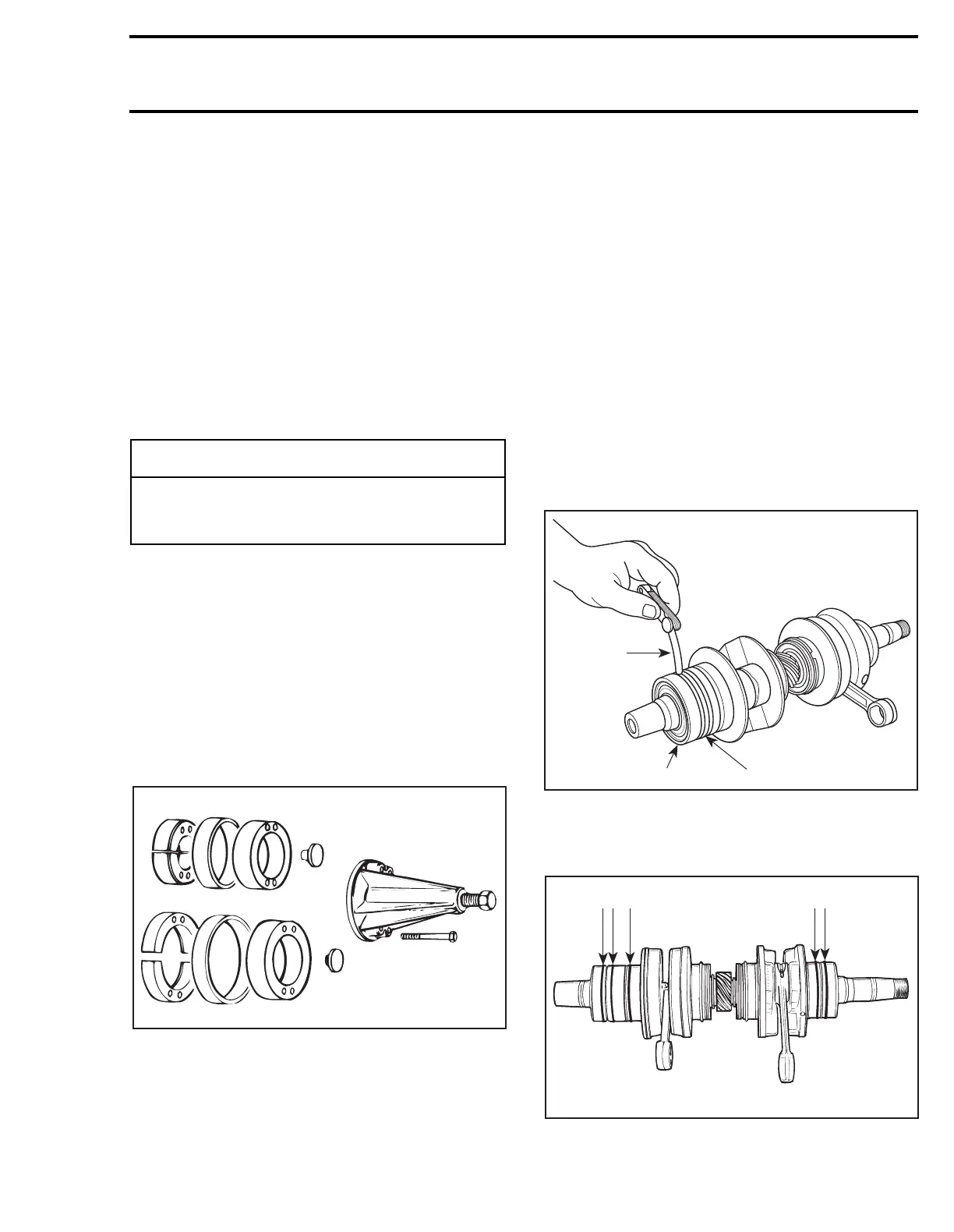
2,4,5,6,9, Crankshaft Bearing and
Labyrinth Sleeve
Smear anti-seize lubricant (P/N 413 7010 00) on
part of crankshaft where bearing fits.
Prior to installation, place bearings into an oil con-
tainer filled with oil previously heated to 75°C
(167°F). This will expand bearing and ease instal-
lation. Install bearings and labyrinth sleeve with
groove as per the following illustration. Keep a
0.3 mm (.012 in) gap between outer bearing and
labyrinth sleeve.
1. Labyrinth sleeve
2. Outer bearing
A. 0.3 mm (.012 in)
Install O-rings as illustrated.
ALL ENGINES EXCEPT 670
-
CAUTION
Never use a sharp object to scrape away old
sealant as score marks incurred are detri-
mental to crankcase sealing.
A00C0HA
1
2
A15C22A
A
2
1
A15C0TA
 Loading...

