Section 08 STEERING/FRONT SUSPENSION
Subsection 02 (STEERING SYSTEM)
08-02-5
To install, stick the heating element to the handle-
bar making sure the wires do not interfere with
operation of the accelerator or brake handle.
Heat the grip with a heater gun or a spotlight to
ease installation. Insert new grip with a rubber
mallet.
INSPECTION
Refer to TESTING PROCEDURE 06-06.
10,16, Ball Joint
(left hand and right hand threads)
Inspect ball joint ends for wear or looseness, if ex-
cessive, replace them.
Screw threaded end of the ball joint into the tie
rod. The maximum external threaded length not
engaged in the tie rod must not exceed the value
L
in the following thread length chart:
TYPICAL
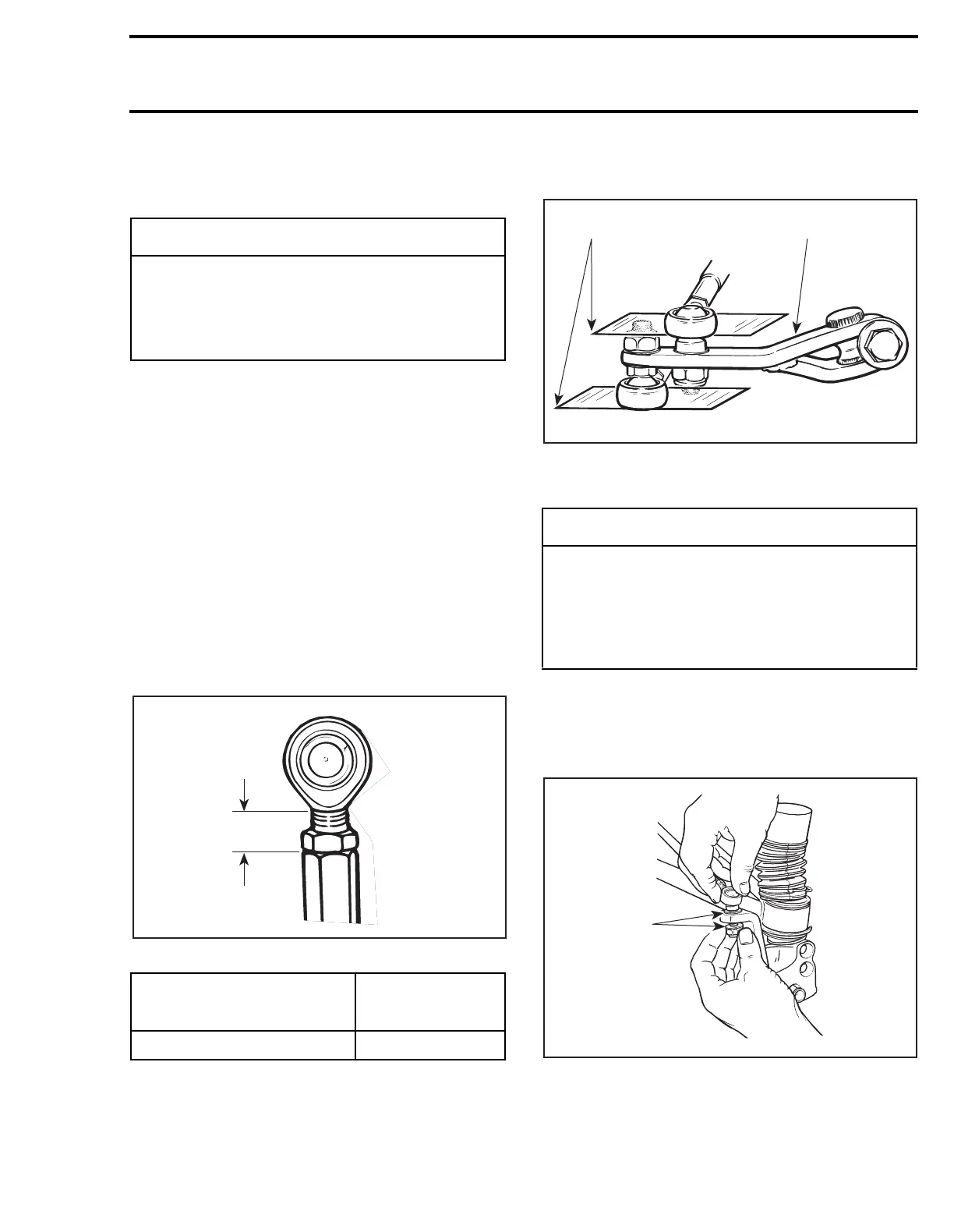
The ball joint should be restrained when tighten-
ing the tie rod end lock nut. Align it so the tie rod
end is parallel to the steering arm when assem-
bled on the vehicle, refer to the following illustra-
tion.
For proper torque specifications refer to the spe-
cific exploded view for the vehicle being serviced.
TYPICAL
1. Parallel with steering arm
2. Steering arm
21, Hardened Washer
All Models Except Skandic WT/SWT/WT LC
Install a hardened washer on each side of the arm.
TYPICAL
1. Hardened washers
◆
WARNING
Never use lubricants (e.g. soap, grease, etc.)
to install the handlebar grip, use a mix of
soap and water. Mix 40 parts of water with
one part of dish washing soap (recom-
mended: Ultra Joy, Sunlight or Palmolive).
MODEL
L
mm (in)
All 20 (25/32)
A17G0SA
L
◆
WARNING
The cut off section of the ball joint must run
parallel with the steering arm. When tighten-
ing lock nuts, restrain ball joint with appro-
priate size wrench. Ensure not too many
threads are kept outside of the tie rod ac-
cording to the thread length chart.
A02G0IA
12
A25G0MA
1
 Loading...

