Section 04 ENGINE
Subsection 03 (494, 583 AND 670 ENGINE TYPES)
04-03-6
NOTE:
Oil dripping from draining hole indicates a
loosened clamp or damaged bellows.
Check for cracked, dried or perforated bellows
no. 9
.
6, Spring
Make sure both springs installed on the engine
have same characteristics.
ASSEMBLY
At assembly, place the pistons over the connect-
ing rods with the letters
AUS
(over an arrow on
the piston dome) facing in direction of the exhaust
port.
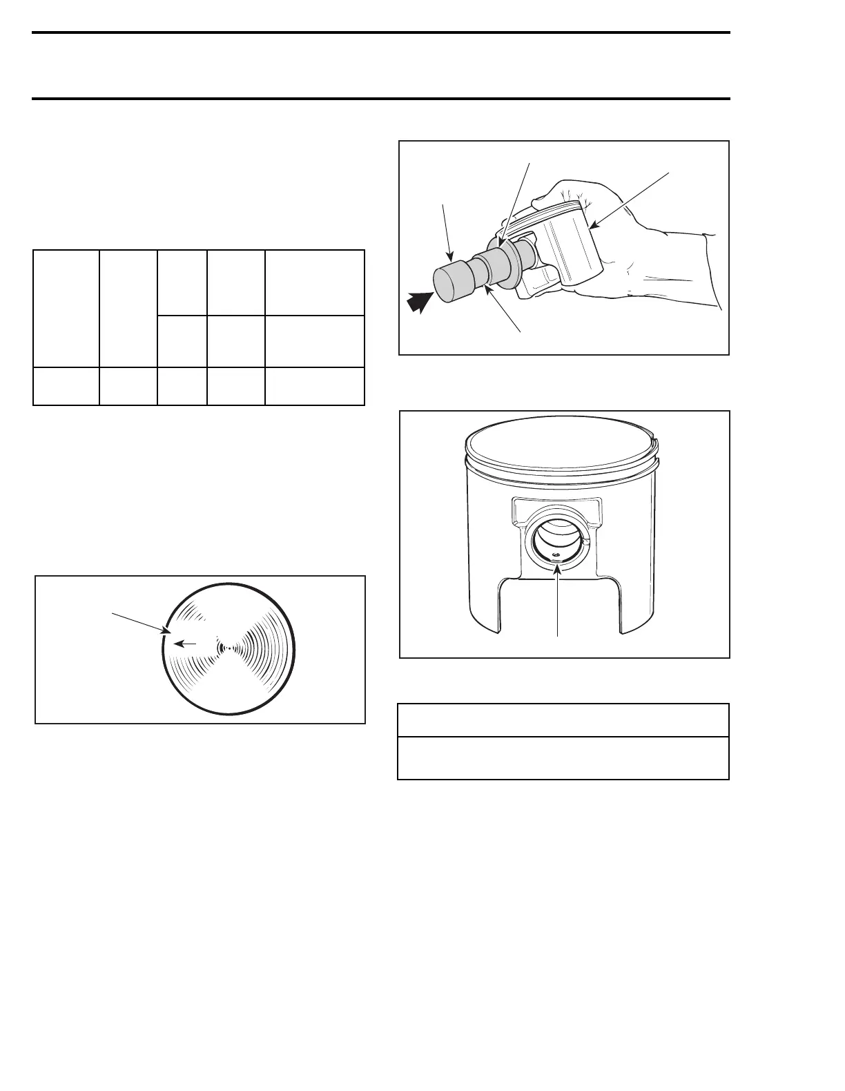
1. Exhaust
Use piston pin puller (P/N 529 0210 00) to ease
piston pin installation.
To minimize the effect of acceleration forces on
circlip, install each circlip so the circlip break is at
6 o’clock as illustrated. Use piston circlip installer
(P/N 529 0169 00) for all engines except 670 and
(P/N 290 8770 16) for 670 engine.
1. Place circlip in
2. Restrain
3. Oil
TYPICAL
1. Circlip break
22, Cylinder
494 Only
To avoid pinching or cutting of O-ring
no. 18
be-
tween cylinder and cylinder head, it is necessary
to use a special tool and to proceed as follows:
Use aligning pin (P/N 529 0189 00).
ENGINE
TYPE
SPRING
P/N
WIRE
DIA.
FREE
LENGTH
PRELOAD IN
N (LBF) AT
COMPRESSED
LENGTH
mm
(in)
mm
(in)
OF
14.7 mm
(.579 in)
583
and 670
420
2399 48
1.0
(.039)
38.0
(1-1/2)
0.0163
(.00365)
A01C01A
AUS
1
-
CAUTION
Circlips must not move freely after installa-
tion; if so, replace them.
A01B1QA
1
2
3
529 0169 00
1
A01C02B
 Loading...

