Section 04 ENGINE
Subsection 12 (FUEL TANK AND THROTTLE CABLE)
04-12-2
Throttle Cable O-ring and Retaining
Ring at Carburetor (some models)
Locate O-ring outside of carburetor cover and re-
taining ring inside.
1. Carburetor cover
2. Throttle cable housing
3. Retaining ring
Adjust throttle cable as specified in CARBURE-
TOR AND FUEL PUMP 04-11.
Throttle Cable Routing
Fuel Level Sensor
Grand Touring 500/583 and Formula Z
INSPECTION
Visually inspect the condition of connectors and
wiring throughout the circuit. Connections must
be clean and tight, and wiring free of damage. Re-
pair as necessary. Use silicone dielectric grease to
prevent corrosion at the connectors. Operate the
engine to see if the problem has been corrected.
If not, remove fuel level sensor from fuel tank and
check rod angle (100.7°), resistance at full posi-
tion (3 ± 2 Ω) and resistance at empty position
(110 ± 7 Ω).
1. Full position (3 ± 2
Ω
)
2. Empty position (110 ± 7
Ω
)
3. Loosen to adjust
FUSE REPLACEMENT
A 0.25 ampere fuse protects fuel level sensor
circuitry. Remove seat to gain access.
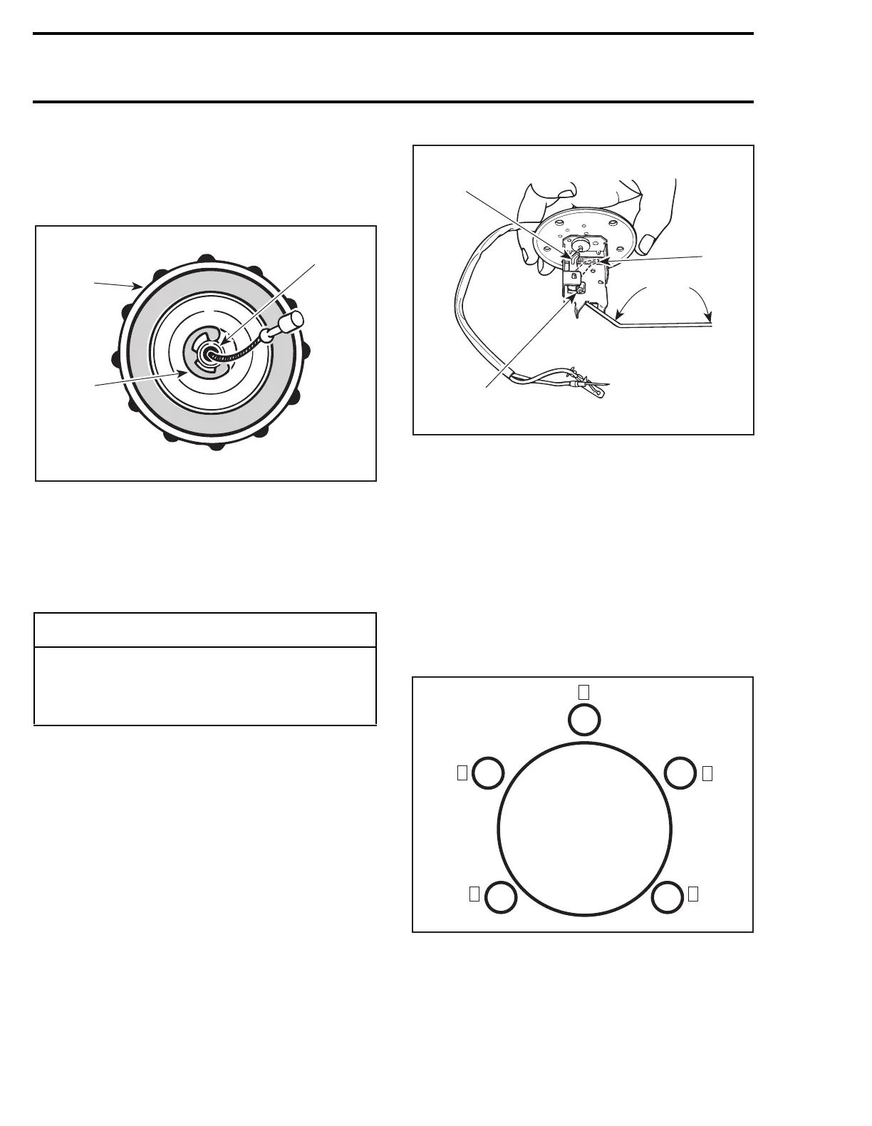
Fuel Level Sensor Screws
Grand Touring 500/583 and Formula Z
Torque fuel level sensor retaining screws to
1 N•m (8 lbf•
in
) in the sequence shown and then
to 2.5 N•m (22 lbf•
in
), using the same sequence.
-
CAUTION
Check that throttle cable is routed away from
sharpedges, hot or vibrating parts. When
turning steering while engine is running,
idle speed must not vary.
A02C0DA
2
1
3
A01E18A
1
3
2
100.7°
A14C02A
1
3
5
4
2
 Loading...

